
Vapor barrier cover for sealing an electrical box against air infiltration

Active Publication Date: 2022-02-22
ARLINGTON INDS
View PDF17 Cites 3 Cited by
  • Summary
  • Abstract
  • Description
  • Claims
  • Application Information

AI Technical Summary

Benefits of technology

The current invention is a vapor barrier cover for sealing electrical boxes during construction. This cover prevents air infiltration without the need for a gasket and can be easily modified if there are changes to the project. It also eliminates the need for reschanging electricians for air prevention during the final phase of construction.

Problems solved by technology

Unfortunately, since drywall has not yet been installed, air infiltration cannot be measured during the rough-in phase.
Unfortunately, this method of reducing air infiltration creates another phase of work after the final phase as the installers must cover each electrical box with an intermediate air infiltration device over each installed electrical box.

Method used


Image

  • Vapor barrier cover for sealing an electrical box against air infiltration
  • Vapor barrier cover for sealing an electrical box against air infiltration
  • Vapor barrier cover for sealing an electrical box against air infiltration

Examples


Embodiment Construction

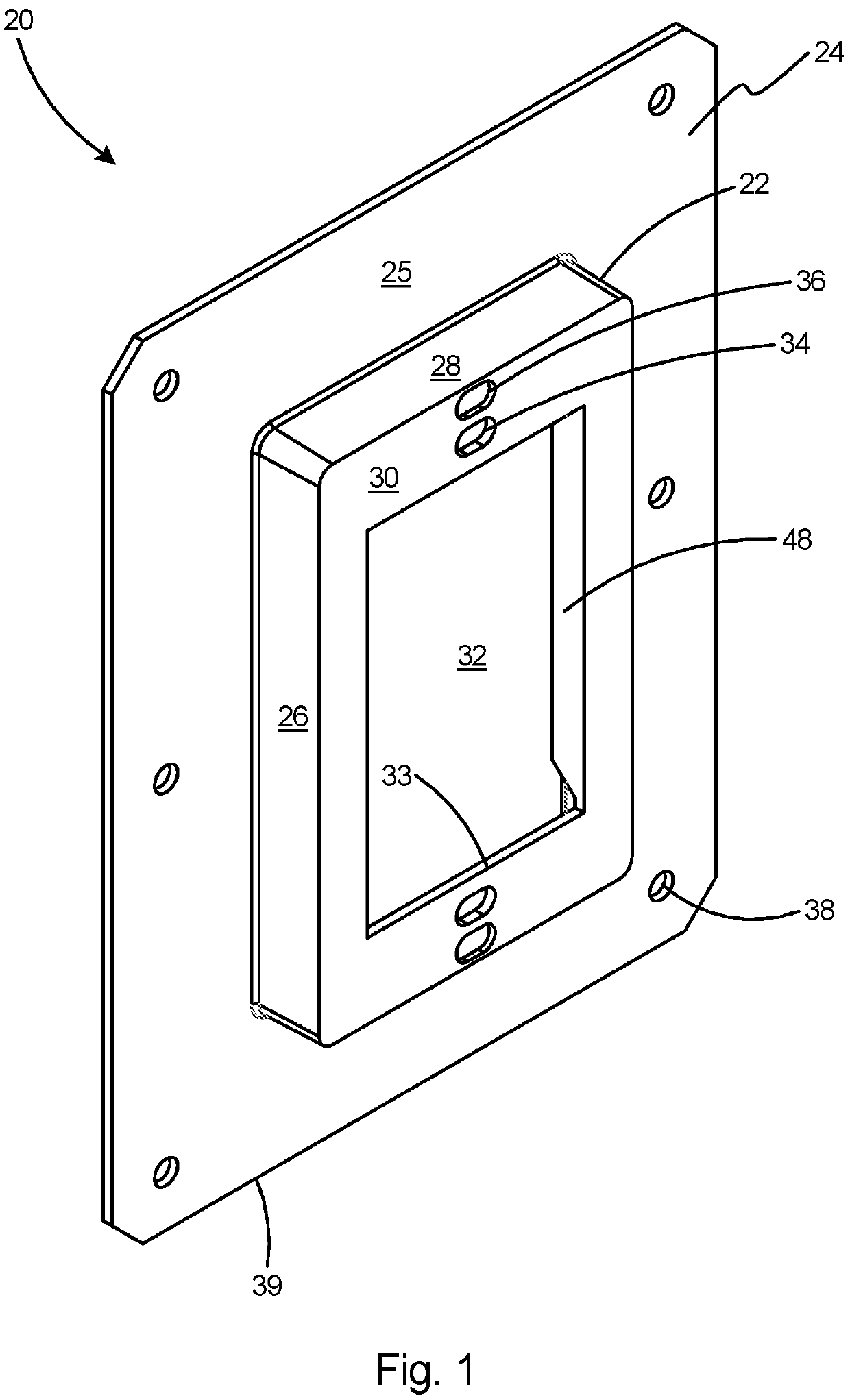
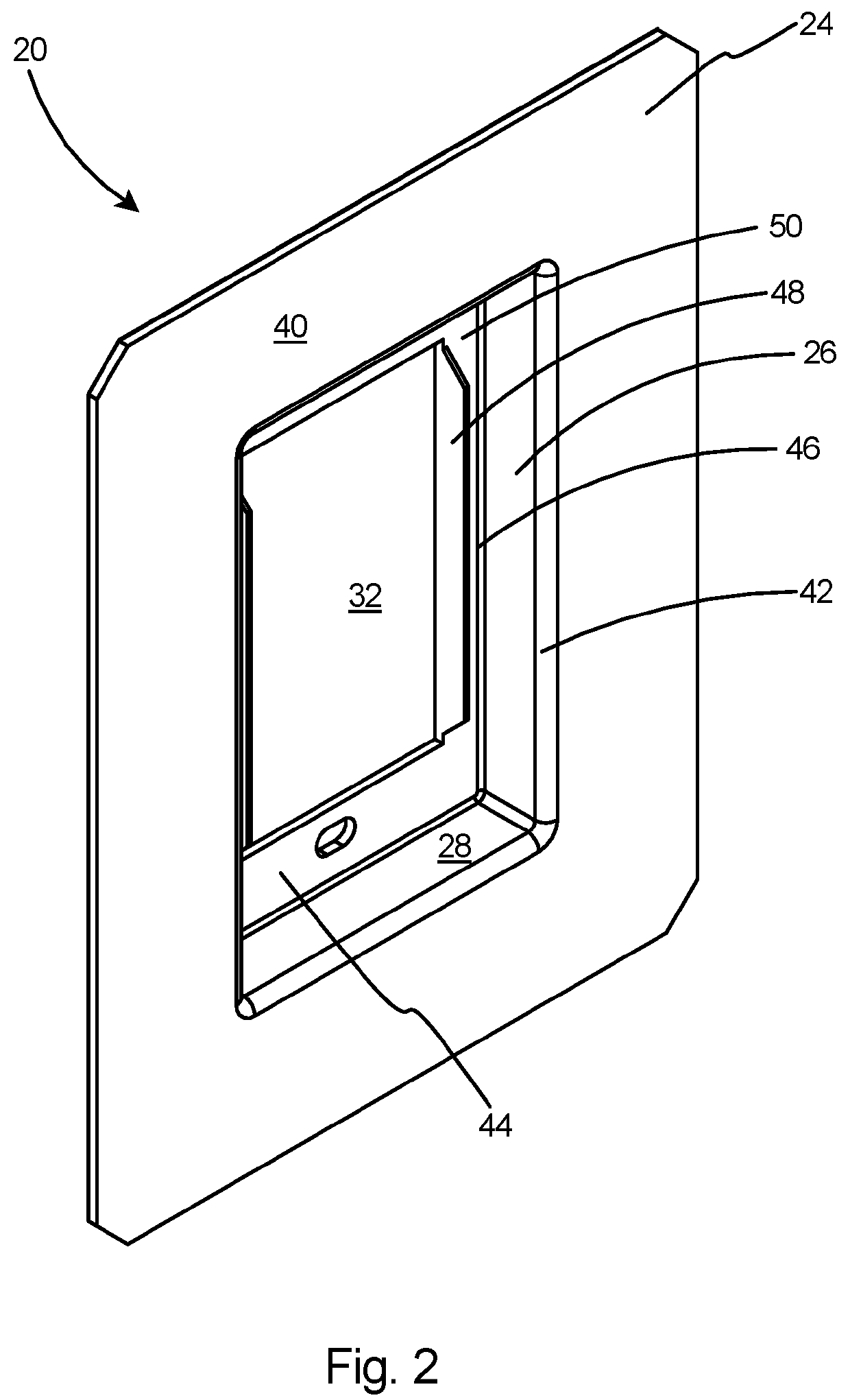
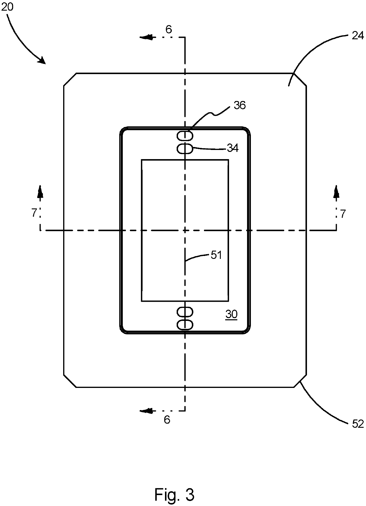
[0030]With reference to FIG. 1, the present invention is a vapor barrier cover 20 for covering a single-gang electrical box and providing a seal between the electrical box and the drywall. The vapor barrier cover 20 includes a body 22 and a flange 24 having a planar front surface 25. Two side walls 26 and two end walls 28 project outward from the flange 24 to a planar front wall 30 having a planar surface and a front opening 32. The front opening 32 is defined by an inner periphery 33 that is an orthogonal rectangle and includes four planar uninterrupted edges. The meaning of the term “uninterrupted edges” as used herein is that there are no deviations in the planar edges such as notches or projections. An inner aperture 34 and flashed-over aperture 36 are provided in the front wall 30. Inner aperture 34 extends through the front wall 30 while flashed-over aperture 36 is skinned-over on the rear surface of the front wall, as will be described herein. One or more flashed-over apertur...


PUM


Abstract

A vapor barrier cover for installation to an electrical box in the rough-in phase of construction. The vapor barrier cover includes a flange with an opening having an inner periphery and a body extending from the inner periphery of the flange. The body includes walls extending to a front edge. A front wall extending from the front edge includes a front opening and a rearward extending wing. Installation of the vapor barrier cover enables inspection and testing for air-tightness around the periphery of the electrical box prior to the final phase of construction and without the need for a gasket.

Description

[0001]This application claims the priority of Provisional U.S. Patent Application Ser. No. 62 / 911,240 filed Oct. 5, 2019, the contents of which are incorporated herein by reference.FIELD OF THE INVENTION[0002]The present invention relates to electrical supply boxes and, and more specifically, to a vapor barrier cover for preventing air infiltration around or through an electrical box.BACKGROUND OF THE INVENTION[0003]In the home building and remodeling trades, the term “rough-in” refers to the stage of construction after the basic framing and the initial wiring and plumbing installations are completed, but before the installation of drywall. This is the point at which much of this work is first reviewed by the building inspector. The absence of wall and floor coverings allows for easier modification if the rough-in does not pass inspection or if the homeowner makes a change order to alter the project.[0004]With regards to the installation of electrical service, a rough-in means that ...

Claims


Application Information

Patent Timeline
IPC IPC(8): H02G3/08
CPCH02G3/088H02G3/081H02G3/126H02G3/14
Inventor GRETZ, THOMAS J.
Owner ARLINGTON INDS
Learn More