
Diagnostic system, fuel cell system having a diagnostic system, and method for determining cathode gas contamination

a fuel cell and diagnostic system technology, applied in the direction of fuel cells, electrical equipment, electrochemical generators, etc., can solve the problems of fuel cell performance loss, affecting the conclusion of influence, and not always known cathode gas quality, etc., to achieve the effect of improving the conclusion of influen

Active Publication Date: 2022-02-08
AUDI AG
View PDF10 Cites 0 Cited by
  • Summary
  • Abstract
  • Description
  • Claims
  • Application Information

AI Technical Summary

Benefits of technology

[0004]Therefore, the present disclosure provides a diagnostic system, a fuel cell system, and a method for determining a cathode gas contamination in a fuel cell system that allow an improved conclusion of the influence of cathode gas quality on the fuel cells.
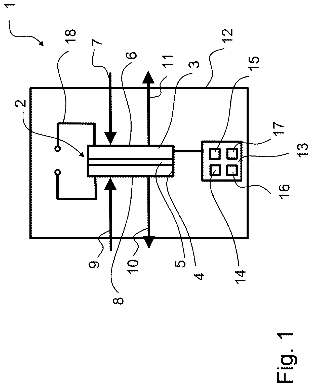
[0007]In some implementations, the diagnostic fuel cell has the same structure as the fuel cells of the fuel cell stack. The individual layers of the diagnostic fuel cell are preferably also formed from the same material as the respective layers of the fuel cells of the fuel cell stack. This allows a better conclusion of the influence of the cathode gas contamination on the fuel cell stack via the diagnostic fuel cell.
[0010]To detect the measured value or the detected measured value curve, in some implementations the detecting unit comprises a voltmeter and / or a current meter, and if the detected measured value or the detected measured value curve is a voltage or a voltage curve generated in the diagnostic fuel cell, and / or a current or a current curve generated in the diagnostic fuel cell. The present disclosure thereby utilizes the effect that a performance loss accompanying the decrease in the cathode gas quality leads to a reduction of the current or voltage generated by the diagnostic fuel cell.
[0012]Some implementations include a fuel cell system with a fuel cell stack, and with a diagnostic system connected with a cathode supply line and an anode supply line. Via the diagnostic system, a possible influence of a cathode gas contamination on the entire fuel cell stack may be concluded by means of a diagnostic fuel cell. Necessary countermeasures may be initiated immediately in order to counteract performance loss and damage to the MEA. This also allows the filters and catalysts of the MEA to be of more compact or smaller design.
[0030]In some implementations, a periodically rising and falling voltage is impressed on the electrode, in particular the cathode, of the diagnostic fuel cell. In a particularly preferred embodiment, a delta voltage is impressed on the electrode of the diagnostic fuel cell. A cyclovoltametric measurement can thereby be carried out at the electrode, in particular at the cathode. This makes it possible to detect sulfur dioxide (SO2) in the cathode gas, for example.

Problems solved by technology

Fuel cells exhibit a loss of performance if cathode gas pollutants, i.e., in particular air pollutants, reach the catalyst.
The problem here is that the cathode gas quality is not always known and varies over both space and time.
At the same time, a loss of performance of the fuel cell may also be ascribed to other factors, i.e., cathode gas contamination is not always a cause of loss of performance.
In the event of a misdiagnosis, restoration operations are unnecessarily performed on the fuel cell.
However, these may damage the membrane electrode assembly (MEA).

Method used


Image

  • Diagnostic system, fuel cell system having a diagnostic system, and method for determining cathode gas contamination
  • Diagnostic system, fuel cell system having a diagnostic system, and method for determining cathode gas contamination
  • Diagnostic system, fuel cell system having a diagnostic system, and method for determining cathode gas contamination

Examples


first embodiment

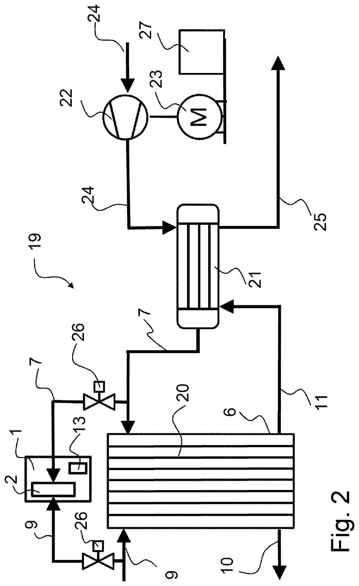
[0049]FIG. 2 shows the fuel cell system 19 according to the present disclosure, with a fuel cell stack 20 and with a cathode supply line 7 for supplying the cathode gas, and an anode supply line 9 for supplying the anode gas. Furthermore, the fuel cell system 19 comprises a humidifier 21 and a compressor 22. Via the compressor 22 driven by means of a motor 23 or an engine, the cathode gas is directed via a dry supply line 24 to the humidifier 21. The cathode supply line 7 connects the humidifier 21 to the fuel cell stack 20 and directs humidified cathode gas—e.g., air—to the cathodes of the fuel cell stack 20. In addition, water and unreacted cathode gas is [sic] directed from the fuel cell stack 20 to the humidifier 21 via a cathode exhaust line 11. The humidifier 21 comprises a plurality of water vapor-permeable membranes that extract the moisture from the cathode gas and supply it to the dry cathode gas for humidification. Finally, the humidifier 21 also has a humidifier discharg...

second embodiment

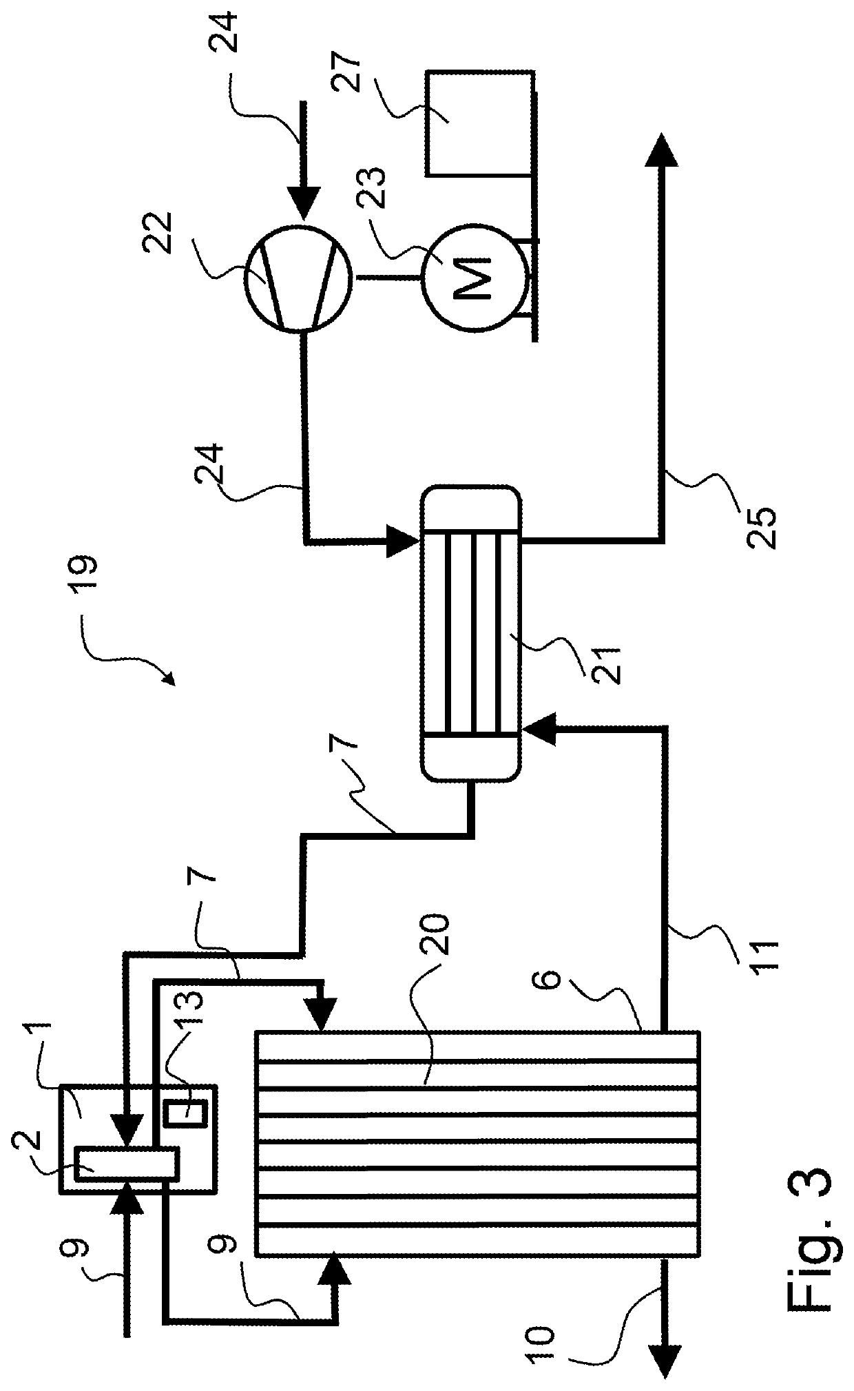
[0053]FIG. 3 shows the fuel cell system 1 according to the present disclosure, wherein the diagnostic system 1 is arranged serially with respect to the fuel cell stack 20. The cathode supply line 7 leads from the humidifier 21 to the diagnostic fuel cell 2, and from there to the cathodes of the fuel cell stack 20. The anode supply line 9 leads from a hydrogen tank (not shown) to the diagnostic fuel cell 2, and from there to the anodes of the fuel cell stack 20. In this embodiment, the anode exhaust line 10 and the cathode exhaust line 11 of the diagnostic system 1 are formed as anode supply line 9 and cathode supply line 7 of the fuel cell stack 20. In this embodiment, the fuel cell stack 20 is also supplied with the same anode gas and cathode gas as the diagnostic system 1.

[0054]The method according to the present disclosure is executed as follows: First, the diagnostic fuel cell 2 is connected with a cathode supply line 7 and an anode supply line 9 of the fuel cell system 19. As a...


PUM

PropertyMeasurementUnit
voltageaaaaaaaaaa
currentaaaaaaaaaa
delta voltageaaaaaaaaaa

Abstract

A diagnostic system for determining the cathode gas quality of a fuel cell system has a fuel cell stack, with a diagnostic fuel cell which can be connected at the cathode side to a cathode supply line and at the anode side to an anode supply line of the fuel cell system. The diagnostic system furthermore comprises a detection unit which is configured to detect a measured value or the measured value time curve of the diagnostic fuel cell operating with the cathode gas provided via the cathode supply line and with the anode gas provided via the anode supply line. The present disclosure moreover relates to a fuel cell system having a diagnostic system, and to a corresponding method.

Description

BACKGROUNDTechnical Field[0001]The present disclosure relates to a diagnostic system for determining the cathode gas quality of a fuel cell system having a fuel cell stack, to a fuel cell system, and to a method for determining a cathode gas contamination in a fuel cell system.Description of the Related Art[0002]Fuel cells exhibit a loss of performance if cathode gas pollutants, i.e., in particular air pollutants, reach the catalyst. The problem here is that the cathode gas quality is not always known and varies over both space and time. At the same time, a loss of performance of the fuel cell may also be ascribed to other factors, i.e., cathode gas contamination is not always a cause of loss of performance. In the event of a misdiagnosis, restoration operations are unnecessarily performed on the fuel cell. However, these may damage the membrane electrode assembly (MEA). In addition, the filters and catalysts of the fuel cell must be designed larger in order to compensate for a loss...

Claims


Application Information

Patent Timeline
Patent Type & Authority Patents(United States)
IPC IPC(8): H01M8/0444H01M8/04537H01M8/04664H01M8/04701H01M8/04828
CPCH01M8/04455H01M8/04544H01M8/04574H01M8/04671H01M8/04679H01M8/04701H01M8/04828Y02E60/50
Inventor SCHMIDT, LASSEKIRSCH, SEBASTIANHÜBNER, GEROLD
Owner AUDI AG
Learn More