Foundry process with hot mold casting

a hot mold casting andfoundry technology, applied in the field of metal casting, can solve the problems of cracks, voids or other defects in the molded parts, and increase the possibility of defects, so as to reduce mold movement, avoid defects, and simplify the process

Active Publication Date: 2022-02-01
SN DETUDE & DE CONSTR DE MOTEURS DAVIATION S N E C M A
View PDF20 Cites 0 Cited by
  • Summary
  • Abstract
  • Description
  • Claims
  • Application Information

AI Technical Summary

Benefits of technology

[0005]The present disclosure is intended to address these disadvantages by proposing a foundry process that will more effectively avoid defects, while reducing mold movement and simplifying the process.
[0007]Thanks to these provisions, the thermal shock of the casting is reduced and the cooling rate of the metal is then reduced, thus limiting the risk of defects due to premature solidification of the metal in the narrowest passages of the mold cavity, while also limiting the movements of the mold and the number of process operations.
[0008]In order to further reduce the risk of defects in the part obtained by this foundry process, the step of cooling and solidifying the metal in the mold held in the main furnace at a pressure below 0.1 Pa can be carried out with a furnace cooling rate lower than or equal to 7° C. / min. Such controlled cooling prevents cracks and other similar defects, particularly caused by the different rates of thermal contraction of the metal and mold material.
[0009]In order to limit the occupancy time of the main furnace by the mold, and thus increase the production rate, the mold preheating step can be performed at least in part in a preheating furnace different from the main furnace.
[0011]The mold can in particular be a shell mold formed around a mold cavity, for example by the so-called lost wax or lost model process. In this case, in order to prevent even more effectively the formation of defects in the part resulting from this process, at least a first part of the mold around the mold cavity may have a wall thickness less than a second part of the mold around the mold cavity. In particular, when the mold is formed by a plurality of superposed layers, as shell molds formed by dipping a pattern several times in a slip bath, the second part of the mold may have a greater number of layers than the first part of the mold. By modulating the wall thickness of the mold in this way, in particular according to the thickness of the cavity at the same location, it is possible to avoid that the different rates of thermal contraction of the metal and the mold material cause excessive mechanical stresses on the metal during cooling and solidification, which could lead to cracks and other similar defects. A local reduction in the wall thickness of the mold, especially around the most vulnerable parts of the metal in the mold cavity, reduces the stresses that the mold can transmit to the underlying metal at these locations during cooling.

Problems solved by technology

With known foundry processes, involving at least one step of casting a metal in the liquid state in a mold, followed by cooling and solidifying the metal in the mold before removing the solidified metal from the mold, defects may occur, particularly when producing components with particularly thin parts, such as the trailing edges of gas turbine blades.
Indeed, the temperature difference between the metal and the mold at the time of casting can cause premature cooling and solidification of a part of the metal in the narrowest passages of the mold cavity, which can cause cracks, voids or other defects in the molded part.
However, the use of such a dedicated preheating furnace requires the removal of the mold from the preheating furnace and its transport to the casting site.
During this extraction and transport, the mold starts to cool, which again increases the possibility of defects.
In addition, these additional operations with a hot mold complicate the foundry process and require additional time and space, while also increasing the risk of workplace accidents.

Method used


Image

  • Foundry process with hot mold casting
  • Foundry process with hot mold casting
  • Foundry process with hot mold casting

Examples


Embodiment Construction

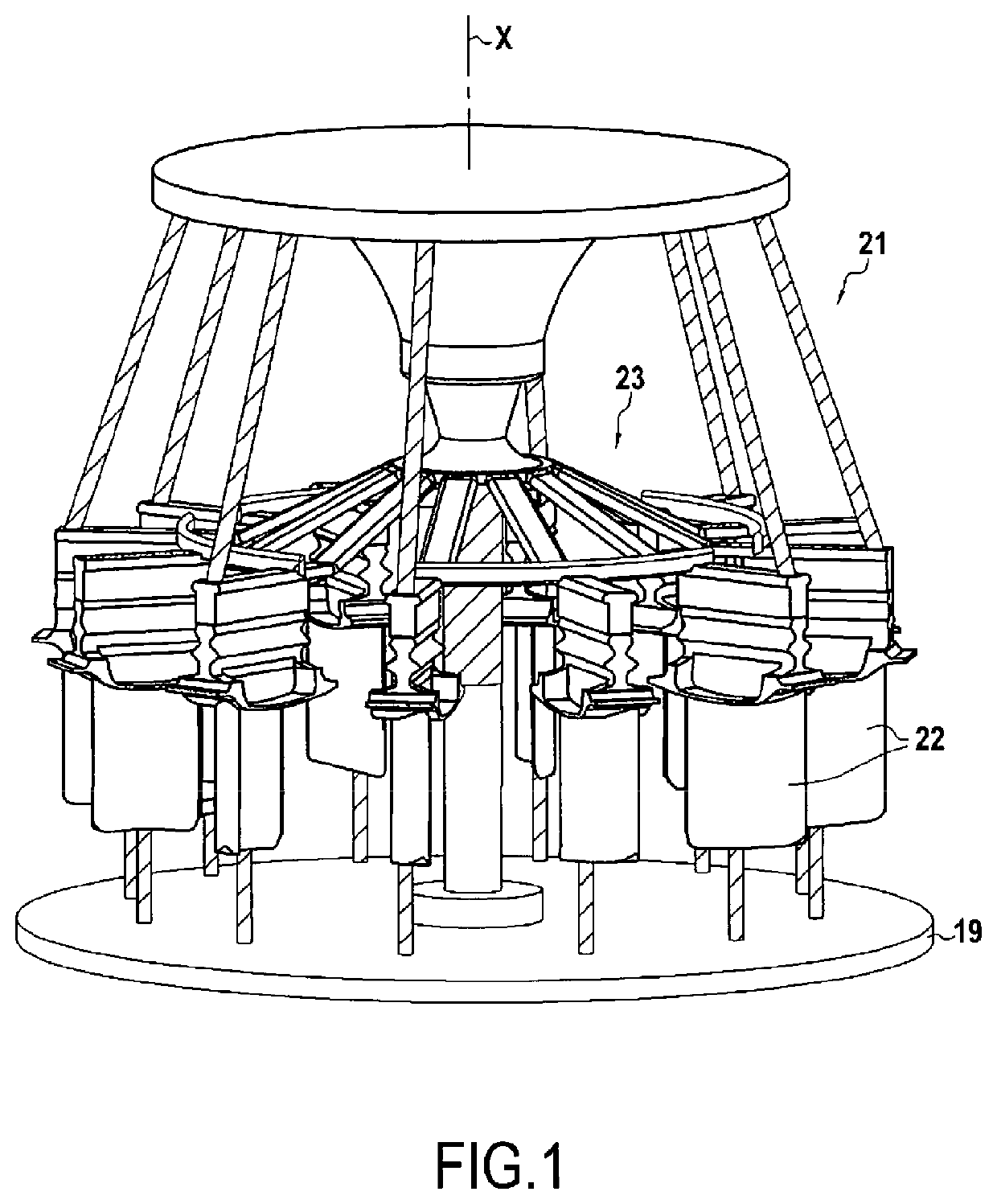
[0024]A first step of a foundry process according to a first embodiment of the invention is the creation of a non-permanent cluster 21 comprising a plurality of models 22 connected by a shaft 23 supported by a tray 19, as shown in FIG. 1. The parts of the shaft 23 intended to form hollow volumes in the mold 1 are formed from a low melting temperature material, such as a wax or modelling resin, while other parts of the shaft 23, forming stiffeners, can be made from refractory material (hatched in FIG. 1). The models 22, which will form mold cavities in the mold, are also formed from a low melting temperature material. When large numbers of components are to be produced, it is possible to produce these elements by injecting wax or modelling resin into a permanent mold. In the embodiment shown, for the production of gas turbine blades, the models 22 represent such blades, with the blade head facing down.

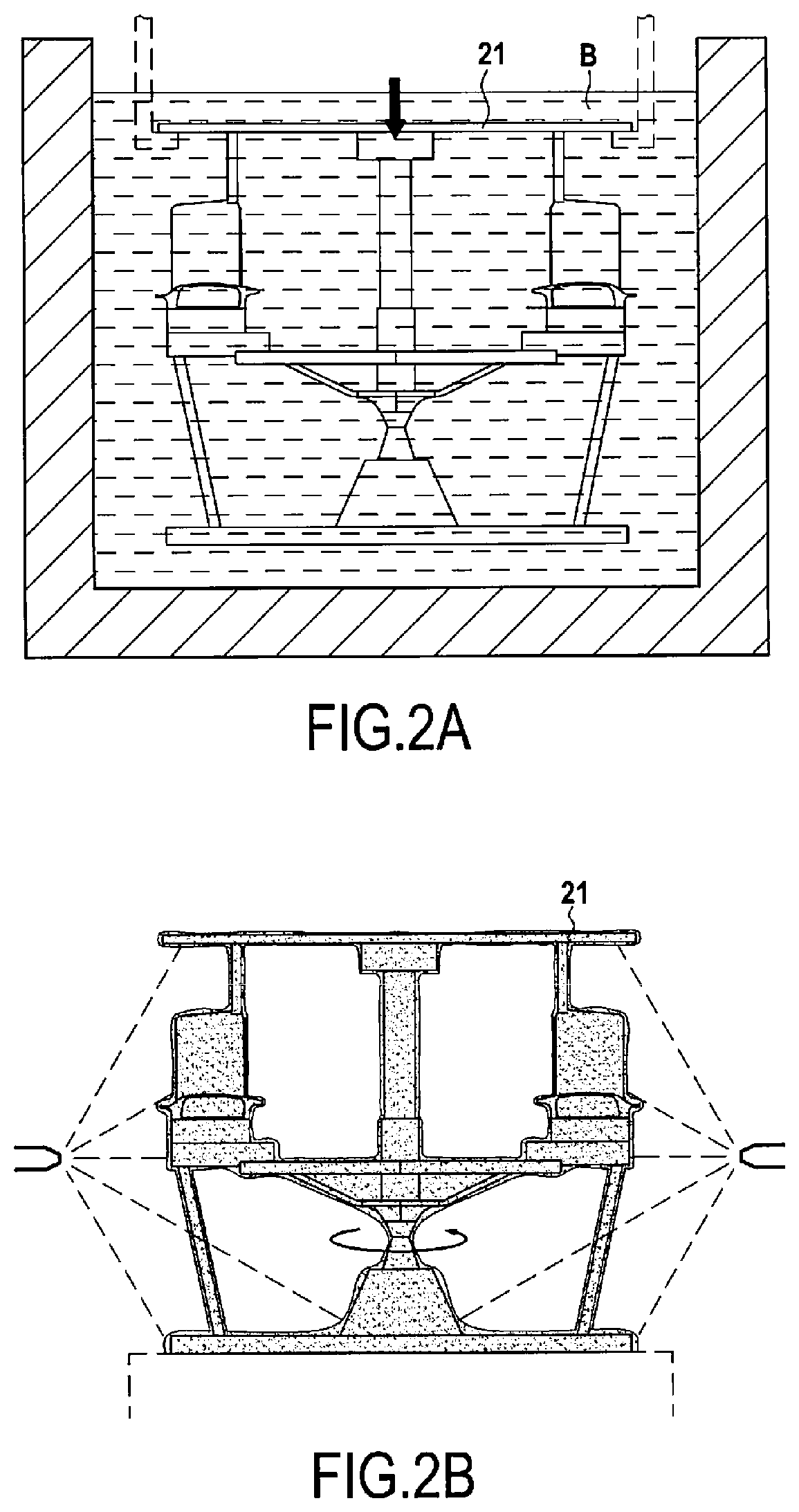
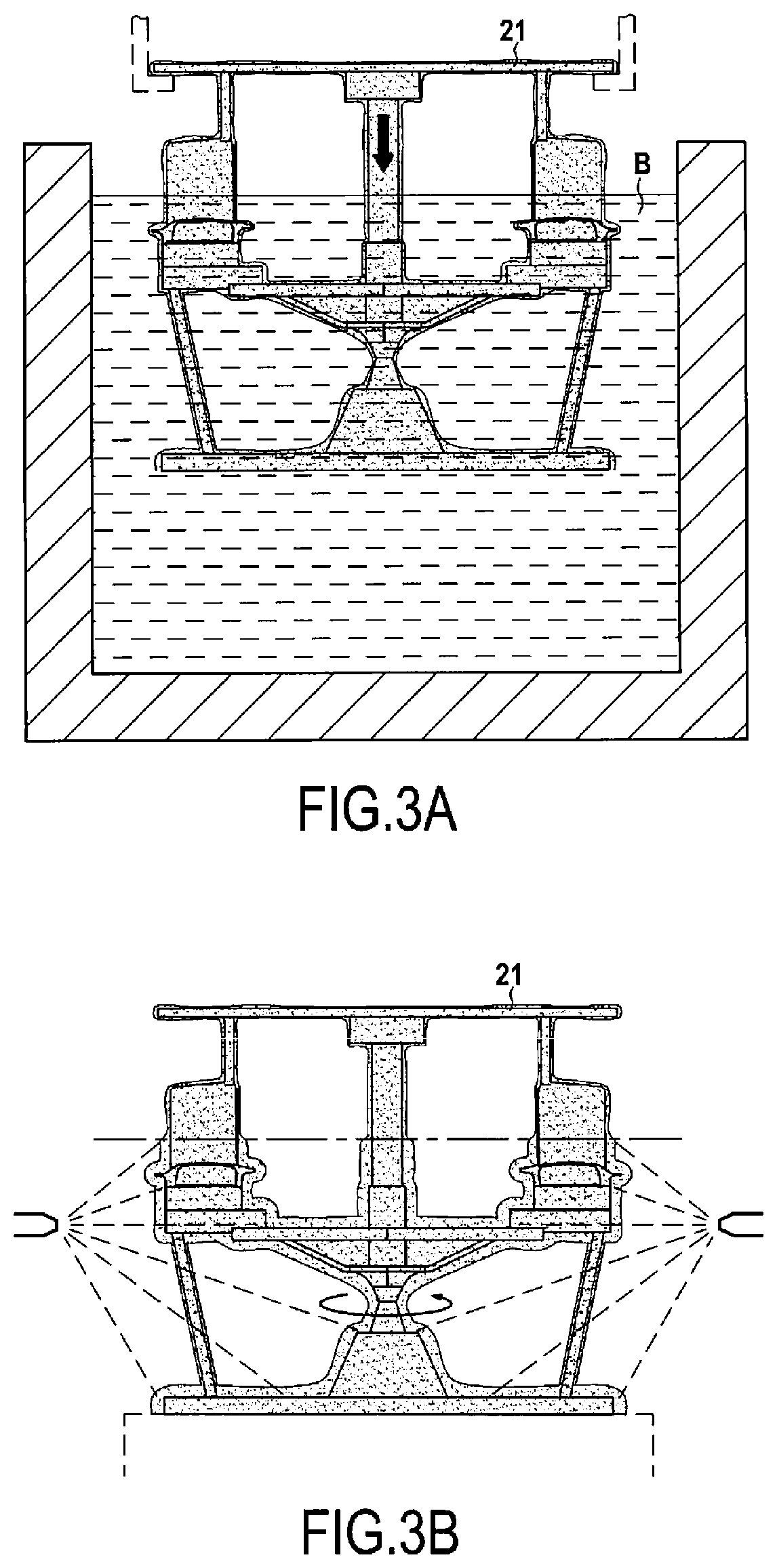
[0025]To produce a mold, more specifically a shell mold, from this non-permanent cl...


PUM

PropertyMeasurementUnit
temperaturesaaaaaaaaaa
pressureaaaaaaaaaa
temperatureaaaaaaaaaa

Abstract

The invention relates to the foundry field, and in particular to a foundry process comprising the preheating of a mold (1) up to a first temperature, the casting of a metal in the liquid state, at a second temperature above the first temperature, in the mold kept in a main furnace (100) at the first temperature since the preheating, the difference between the first temperature and second temperature being no more than 80° C., the cooling and solidification of the metal in the mold (1) kept in the main furnace (100) at a pressure of less than 0.1 Pa at least since the casting, the removal of the mold (1) from the main furnace (100), and the demolding of the solidified metal.

Description

CROSS-REFERENCE TO RELATED APPLICATION(S)[0001]This application is the U.S. national phase entry under 35 U.S.C. § 371 of International Application No. PCT / FR2018 / 051617, filed on Jun. 29, 2018, which claims priority to French Patent Application No. 1755990, filed on Jun. 29, 2017.BACKGROUND OF THE INVENTION[0002]The present invention relates the field of metal casting. In the present context, “metal” refers to both pure metals and metal alloys.[0003]With known foundry processes, involving at least one step of casting a metal in the liquid state in a mold, followed by cooling and solidifying the metal in the mold before removing the solidified metal from the mold, defects may occur, particularly when producing components with particularly thin parts, such as the trailing edges of gas turbine blades. Indeed, the temperature difference between the metal and the mold at the time of casting can cause premature cooling and solidification of a part of the metal in the narrowest passages o...

Claims


Application Information

Patent Timeline
Patent Type & Authority Patents(United States)
IPC IPC(8): B22C9/04B22D27/04B22C9/12B22C13/08B22D21/02
CPCB22C9/12B22C9/04B22C13/08B22D21/025B22D27/04B22D27/045
Inventor FARGEAS, SERGE ALAINTENNE, SERGECOYEZ, DOMINIQUE
Owner SN DETUDE & DE CONSTR DE MOTEURS DAVIATION S N E C M A
Why Eureka
Try Eureka