
Automated diagnostics of electronic instrumentation in a system for fracturing a well and associated methods

a technology of electronic instruments and fracturing wells, which is applied in the direction of fluid removal, borehole/well accessories, construction, etc., can solve the problems of failure of formation and fracture, inability to operate equipment while operating, and rapid pressure increase, so as to facilitate equipment maintenance, maintenance schedule and troubleshooting, and ensure the operation accuracy of electronic instruments

Active Publication Date: 2022-01-11
BJ ENERGY SOLUTIONS LLC
View PDF1082 Cites 54 Cited by
  • Summary
  • Abstract
  • Description
  • Claims
  • Application Information

AI Technical Summary

Benefits of technology

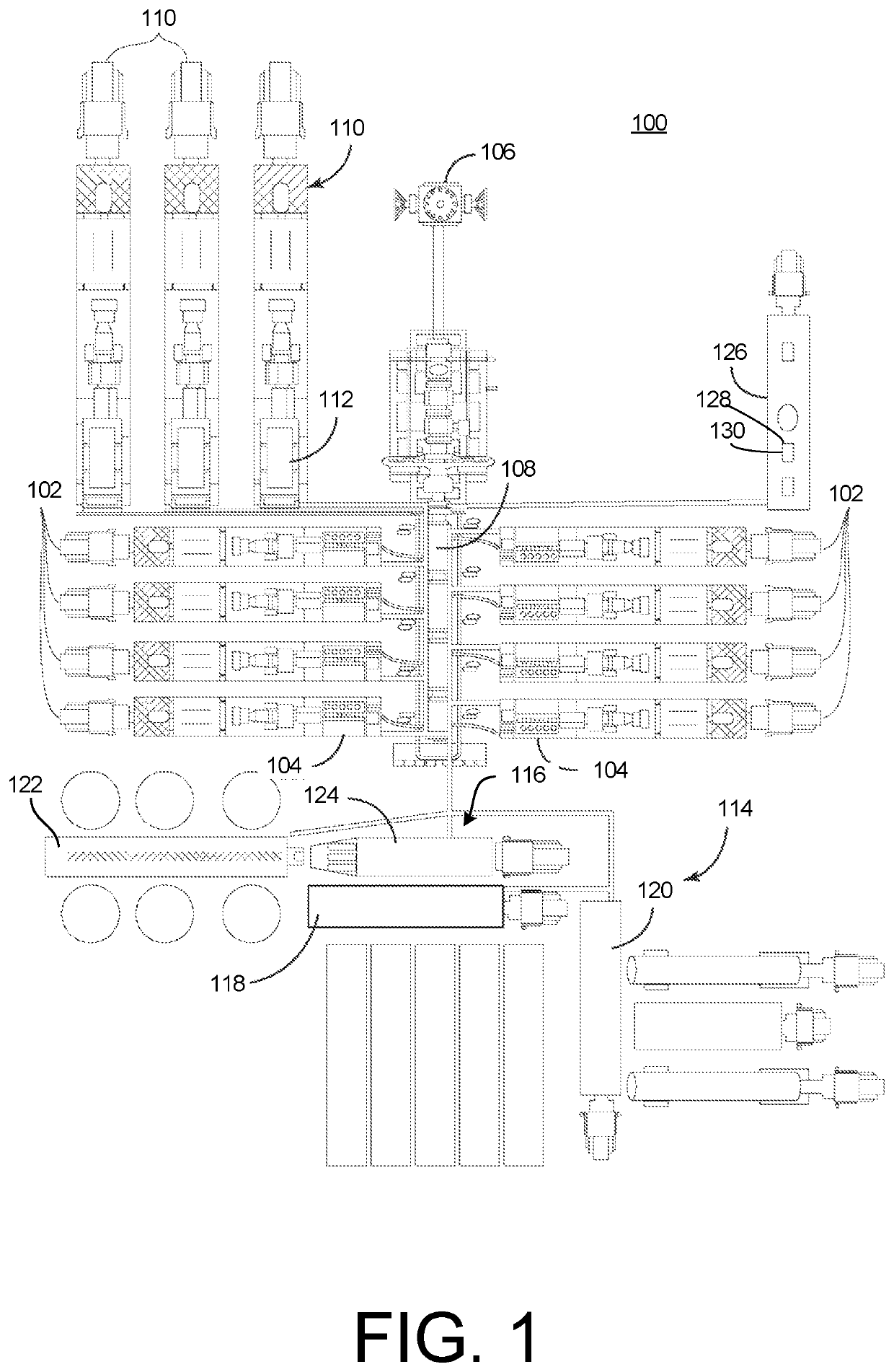
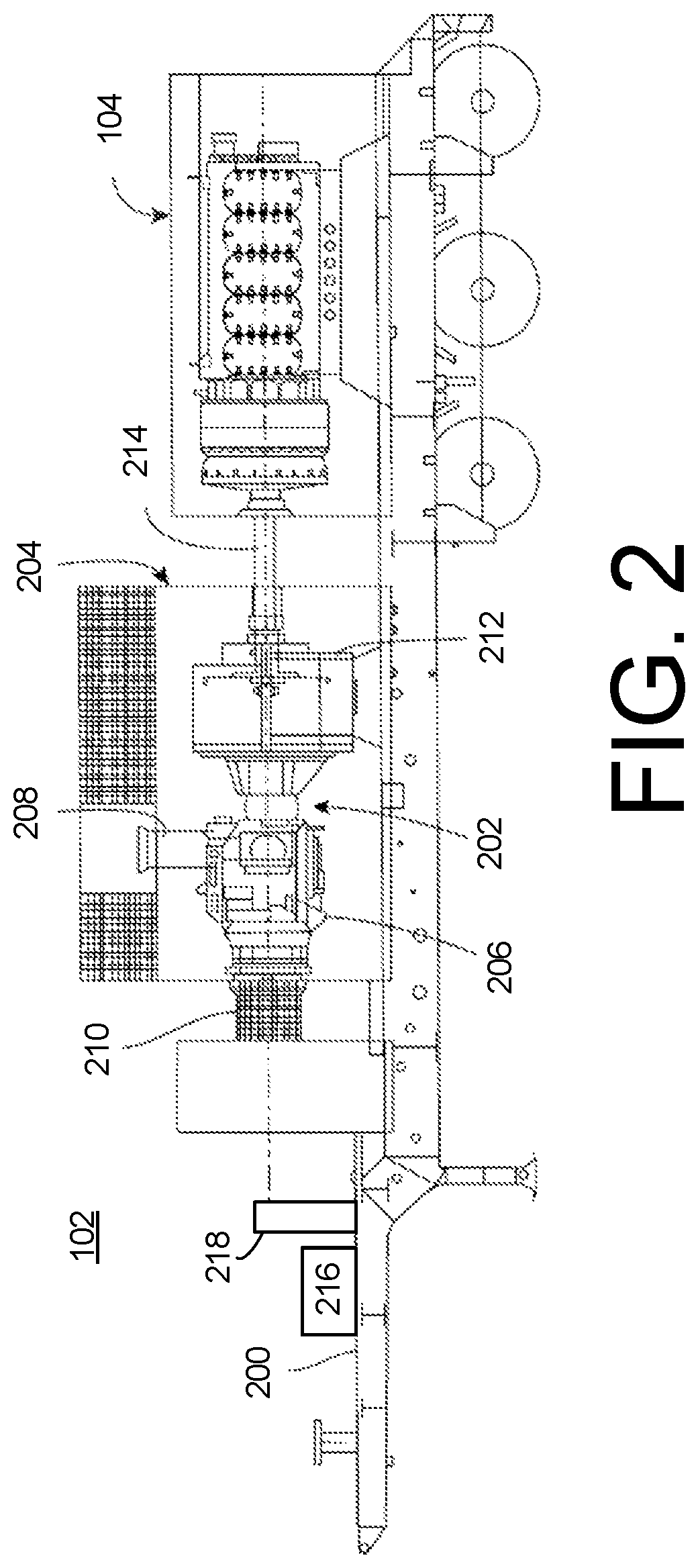
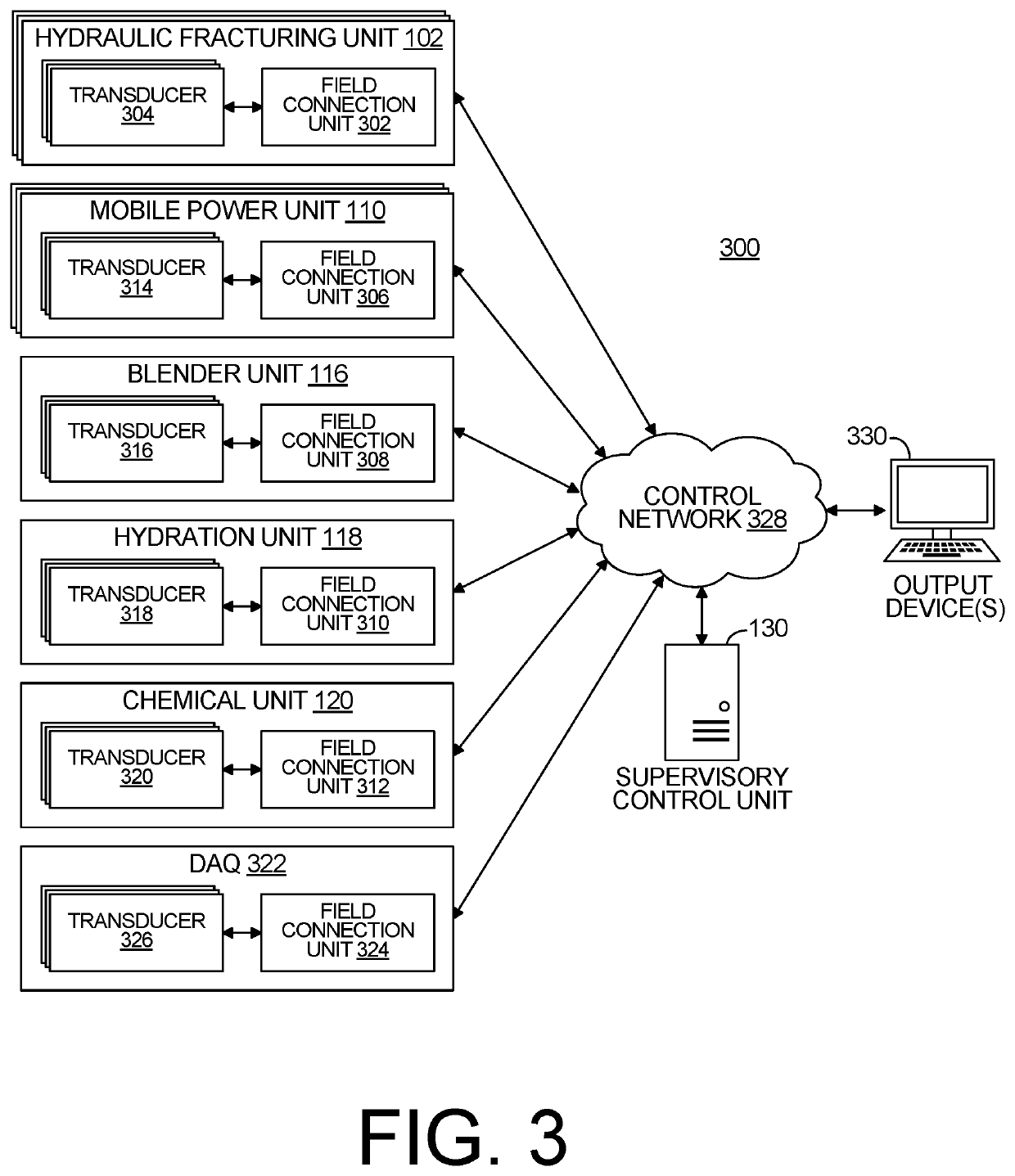
[0006]Example implementations of the present disclosure provide a supervisory control unit and associated method for performing automated diagnostics of physical components and / or electronic instrumentation, such as one or more of transducers onboard one or more hydraulic fracturing units or otherwise distributed throughout a system for fracturing a well. The diagnostics may facilitate equipment maintenance, maintenance schedules and troubleshooting, and may ensure operational accuracy of the electronic instrumentation. The present disclosure includes, without limitation, the following example implementations.

Problems solved by technology

As a result, pressure builds rapidly to the point where the formation fails and begins to fracture.
This cannot be done while operating the equipment as this would disrupt the use of the transducer.
One detrimental condition may include high vibration on a fracturing pump during a fracturing stage.

Method used


Image

  • Automated diagnostics of electronic instrumentation in a system for fracturing a well and associated methods
  • Automated diagnostics of electronic instrumentation in a system for fracturing a well and associated methods
  • Automated diagnostics of electronic instrumentation in a system for fracturing a well and associated methods

Examples


Embodiment Construction

[0030]Some implementations of the present disclosure will now be described more fully hereinafter with reference to the accompanying figures, in which some, but not all, implementations of the disclosure are shown. Indeed, various implementations of the disclosure may be embodied in many different forms and should not be construed as limited to the implementations set forth herein; rather, these example implementations are provided so that this disclosure will be thorough and complete, and will fully convey the scope of the disclosure to those skilled in the art. Like reference numerals refer to like elements throughout.

[0031]Unless specified otherwise or clear from context, references to first, second, or the like should not be construed to imply a particular order. A feature described as being above another feature (unless specified otherwise or clear from context) may instead be below, and vice versa; and similarly, features described as being to the left of another feature may i...


PUM


Abstract

Systems and methods for identifying a status of components of hydraulic fracturing units including a prime mover and a hydraulic fracturing pump to pump fracturing fluid into a wellhead via a manifold may include a diagnostic control assembly. The diagnostic control assembly may include sensors associated with the hydraulic fracturing units or the manifold, and a supervisory control unit to determine whether the sensors are generating signals outside a calibration range, determine whether a fluid parameter associated with an auxiliary system of the hydraulic fracturing units is indicative of a fluid-related problem, determine whether lubrication associated with the prime mover, the hydraulic fracturing pump, or a transmission of the hydraulic fracturing units has a lubrication fluid temperature greater than a maximum lubrication temperature, or determine an extent to which a heat exchanger assembly associated with the hydraulic fracturing units is cooling fluid passing through the heat exchanger assembly.

Description

PRIORITY CLAIM[0001]This U.S. Non-Provisional patent application claims priority to and the benefit of, under 35 U.S.C. § 119(e), U.S. Provisional Application No. 62 / 705,375, filed Jun. 24, 2020, titled “AUTOMATED DIAGNOSTICS OF ELECTRONIC INSTRUMENTATION IN A SYSTEM FOR FRACTURING A WELL AND ASSOCIATED METHODS,” the disclosure of which is incorporated herein by reference in its entirety.TECHNOLOGICAL FIELD[0002]This disclosure relates generally to fracturing operations for oil and gas wells, and in particular, to controls for and diagnostics of electronic instrumentation in a system for fracturing a well and associated methods.BACKGROUND[0003]Fracturing is an oilfield operation that stimulates production of hydrocarbons, such that the hydrocarbons may more easily or readily flow from a subsurface formation to a well. For example, a fracturing system may be configured to fracture a formation by pumping a fracking fluid into a well at high pressure and high flow rates. Some fracking ...

Claims


Application Information

Patent Timeline
Patent Type & Authority Patents(United States)
IPC IPC(8): E21B43/26E21B47/07
CPCE21B43/2607E21B47/07
Inventor YEUNG, TONYRODRIGUEZ-RAMON, RICARDOALVAREZ, ANDRES
Owner BJ ENERGY SOLUTIONS LLC
Learn More