
Optical writing device

a writing device and optical technology, applied in the field of optical writing devices, can solve the problems of deterioration of the image formed with the image carrier, and does not take into account how, so as to reduce or prevent the deterioration of the electrostatic latent image formed

Active Publication Date: 2022-01-04
KONICA MINOLTA INC
View PDF6 Cites 0 Cited by
  • Summary
  • Abstract
  • Description
  • Claims
  • Application Information

AI Technical Summary

Benefits of technology

Prevents deterioration of the electrostatic latent image by ensuring that the imaging mode is consistent and data-dependent, thereby improving image quality and resolution.

Problems solved by technology

However, the technique described in JP 2004-074515 A does not take into consideration how the light from each light-emitting element forms an image on the image carrier.
If the photosensitive mode of the image carrier changes due to a factor other than the data of the image to be formed, the electrostatic latent image formed on the image carrier might deteriorate, which might lead to deterioration of the image formed with the image carrier.

Method used


Image

  • Optical writing device
  • Optical writing device
  • Optical writing device

Examples


Embodiment Construction

[0020]Hereinafter, one or more embodiments of an optical writing device will be described with reference to the drawings. However, the scope of the invention is not limited to the disclosed embodiments. In the description below, like components and constituent elements are denoted by like reference numerals. Like components and constituent elements also have like names and functions. Therefore, explanation of them will not be unnecessarily repeated.

[0021][1. Configuration of an Optical Writing Device]

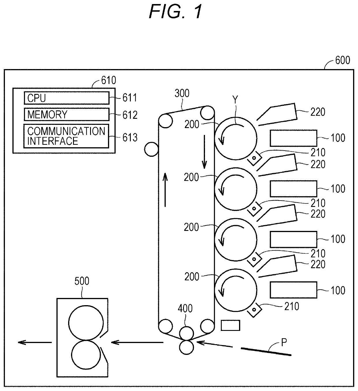
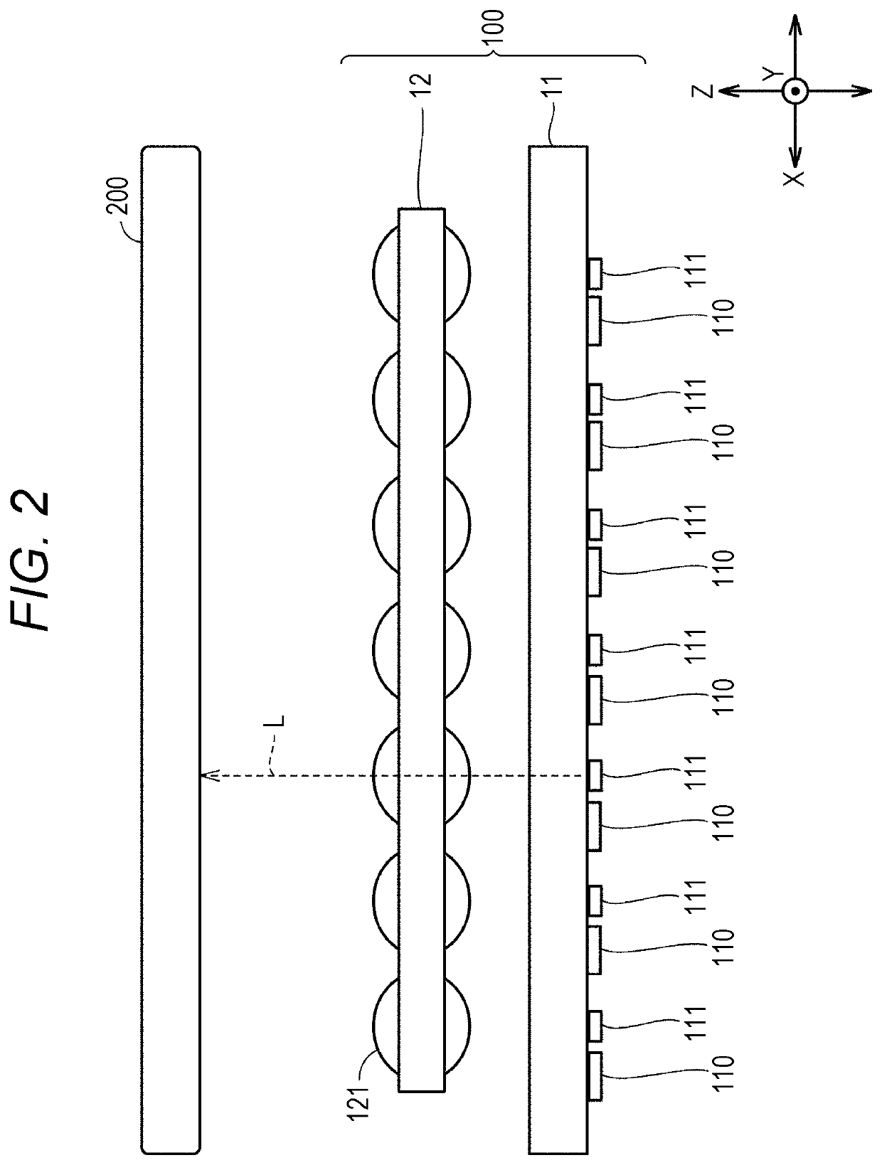
[0022]FIG. 1 is a diagram schematically showing the configuration of an image forming apparatus that is an example of an optical writing device. An image forming apparatus 600 is a printer or a digital copying machine, for example. As shown in FIG. 1, the image forming apparatus 600 includes: a plurality of optical writing units 100 provided for the respective colors of cyan, magenta, yellow, and black; photosensitive members (image carriers) 200 such as photosensitive drums provided fo...


PUM

PropertyMeasurementUnit
angleaaaaaaaaaa
incident angleaaaaaaaaaa
angleaaaaaaaaaa

Abstract

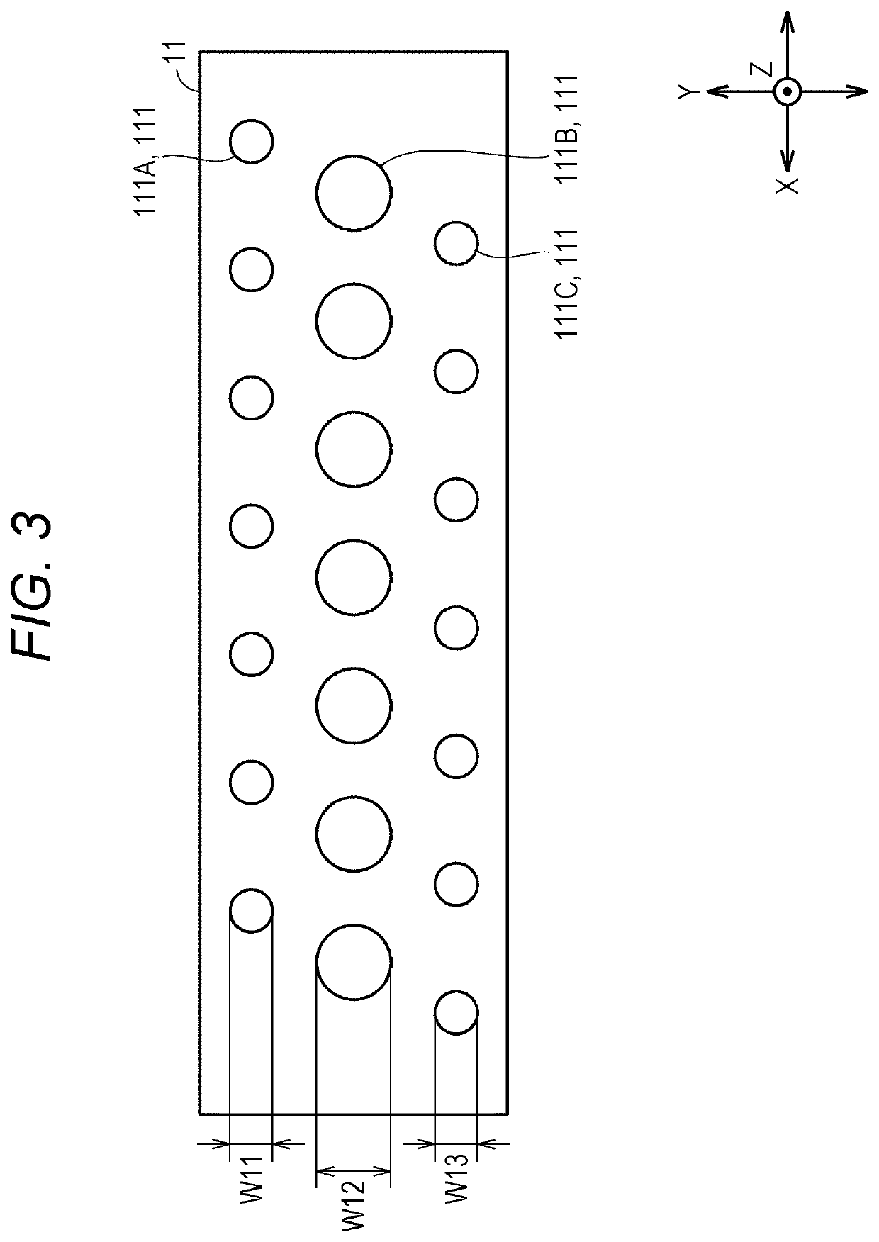
An optical writing device includes: an image carrier; an exposer that exposes a curved surface of the image carrier; and a control circuit that controls the exposer, wherein the exposer includes a plurality of light-emitting element groups having different positional relationships from one another with the image carrier, and has a configuration that is adjusted in accordance with at least one of an angle at which light reaching the curved surface of the image carrier from each light-emitting element group enters the image carrier, and a distance of each light-emitting element group from the image carrier.

Description

[0001]The entire disclosure of Japanese patent Application No. 2019-010224, filed on Jan. 24, 2019, is incorporated herein by reference in its entirety.BACKGROUNDTechnological Field[0002]The present disclosure relates to an optical writing device, and more particularly, to an optical writing device that optically writes information on an image carrier.Description of the Related Art[0003]Regarding image forming apparatuses (multi-functional peripherals (MFPs), for example), there are various techniques suggested for writing optical information on an image carrier (a photosensitive member, for example). For example, JP 2004-074515 A discloses a technique for an image forming apparatus that writes information on an image carrier by irradiating the image carrier with light from respective light-emitting elements via a lens. By this technique, the sizes of the respective light-emitting elements vary with distances from the central axis of the lens.[0004]However, the technique described i...

Claims


Application Information

Patent Timeline
Patent Type & Authority Patents(United States)
IPC IPC(8): G03G15/04G03G15/043
CPCG03G15/04063G03G15/0435G03G2215/0412
Inventor HASEGAWA, RYOMATSUO, TAKAHIROTANIGUCHI, HAJIMENAGAOKA, ATSUSHI
Owner KONICA MINOLTA INC
Learn More