
Locking mechanism for hemostasis device

a technology of hemostasis and locking mechanism, which is applied in the field of locking mechanism, can solve the problems of premature release of compressive force, each procedures requires extensive interaction, and none of these prior art devices provides the clinician with a devi

Active Publication Date: 2021-12-28
FORGE MEDICAL
View PDF21 Cites 0 Cited by
  • Summary
  • Abstract
  • Description
  • Claims
  • Application Information

AI Technical Summary

Benefits of technology

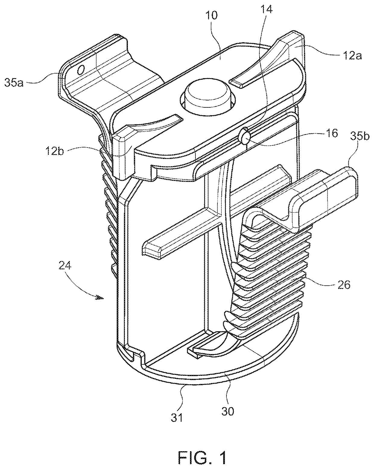
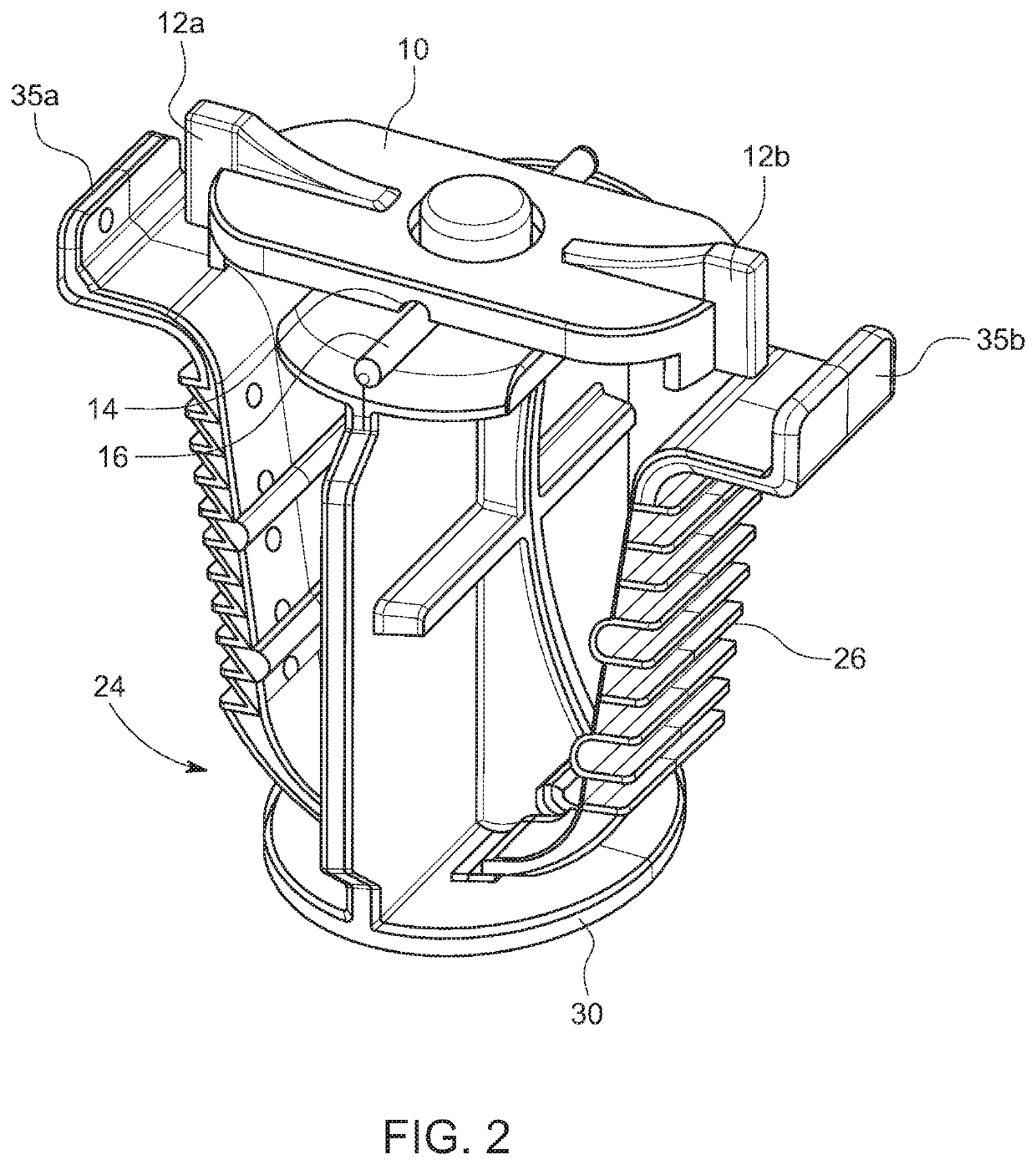
[0008]A locking mechanism for hemostasis devices, such as the VasoStat™ hemostasis device, is provided. In one embodiment, the locking mechanism comprises an elongated tab rotatably affixed to the top of the plunger by means of a pin. The tab is configured to be rotated 90° about the pin between a first, unlocked position, and a second, locked position. With the plunger depressed and the ratcheted wings engaged, the locking mechanism in rotated from the first position to the second position, thereby restricting the inward movement and disengagement of the ratcheted wings.
[0010]In yet another embodiment, the locking mechanism may comprise a retaining bar pivotably connected to one of the ratcheted wings and configured to be releasably connected to the other ratcheted wing. With the plunger depressed and the ratcheted wings engaged, the retaining bar in pivoted from the first (disengaged) position into the second (engaged) position, thereby restricting the inward movement and disengagement of the ratcheted wings.
[0011]In still another embodiment, the locking mechanism may comprise a hinged member incorporated into the body or edge of the cylinder and configured to be releasably connected to the plunger. With the plunger depressed and the ratcheted wings engaged, the hinged member is rotated from a first (disengaged) position into the second (engaged) position, thereby restricting the inward movement and disengagement of the ratcheted wings.

Problems solved by technology

Each of these prior art devices and procedures requires extensive interaction with a patient by a clinician.
None of these prior art devices provides the clinician with a device that can be applied with a single hand in a manner that allows the clinician to simultaneously remove the vascular access sheath so that hemostasis is achieved.
Disoriented or uncooperative patients, however, may seek to disengage the ratcheted wings and, in doing so, may prematurely release the compressive force.

Method used


Image

  • Locking mechanism for hemostasis device
  • Locking mechanism for hemostasis device
  • Locking mechanism for hemostasis device

Examples


Embodiment Construction

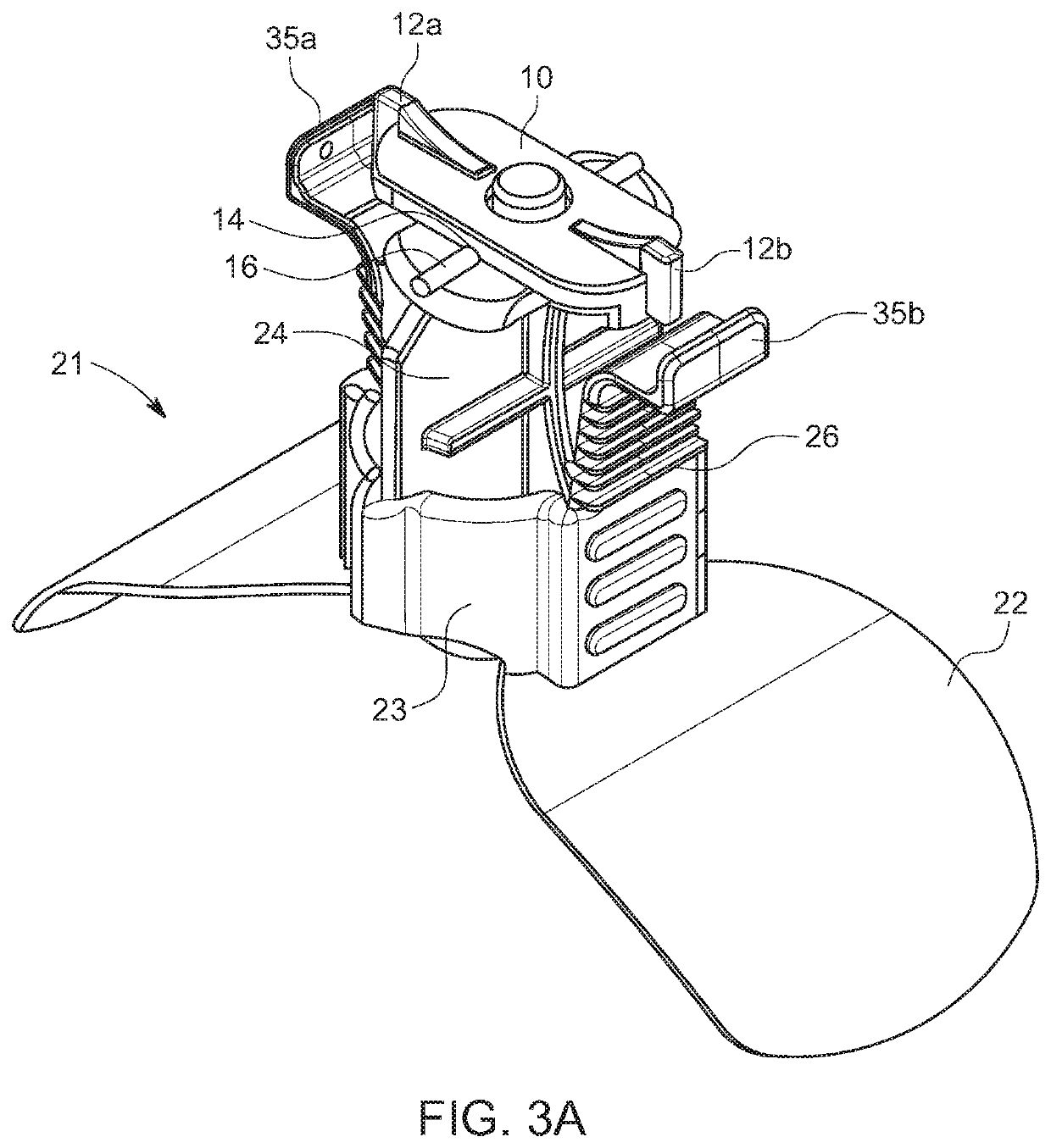
[0030]As shown in the embodiment illustrated in FIGS. 1A-1C, 2A, 2B, 3A-3D, and 4A-4E, the locking mechanism comprises an elongated tab 10 rotatably affixed to the top of the plunger 24 of a VasoStat™ hemostasis device. The elongated tab 10 may be affixed by means of a pin, a locking snap fastener, or other such suitable connector (not shown), and is configured to be rotatable between a first, unlocked position, and a second, locked position. In the first, unlocked position, as shown in FIGS. 1A-1C, the ratcheted wings 35a and 35b attached to the base of the plunger 24 are not restricted in their inward movement. When rotated into the second, locked position, as shown in FIGS. 2A, 2B, and 3A-3D, the elongated tab 10 is oriented such that the top ends of the ratcheted wings 35a and 35b are restricted from inward movement. So restricted, the plunger 24 cannot be disengaged and the compressive force is maintained.

[0031]FIGS. 4A-4E show the progression of rotation of the elongated tab 1...


PUM


Abstract

An accessory for a VasoStat™ hemostasis device that locks the plunger within the cylinder through which the plunger travels by restricting disengagement of ratcheted wings affixed to the plunger. The accessory may be repositioned or removed so that the ratcheted wings may be disengaged and the plunger may be retracted within the cylinder. When integrated into the plunger, the accessory may be configured to move between a first unlocked position and a second locked position. As a separate component, the accessory is configured to be positioned over and locked into position on the hemostasis device, such as the central stem of the plunger.

Description

FIELD OF THE INVENTION[0001]The present disclosure relates to locking mechanisms for devices that adhere to a patient's skin at a vascular access site and apply a compressive force to the puncture site to achieve hemostasis, and particularly to mechanisms used for releasably locking hemostasis devices while applying hemostatic compression to a patient.BACKGROUND[0002]There are many devices and procedures currently employed in the medical field for achieving hemostasis at a percutaneous vascular access site resulting, for example, from a transradial cardiac catheterization procedure.[0003]Among such prior art devices and procedures are, for example: a non-woven sponge manually applied directly to the site of the bleeding at the puncture site; band-type devices tightened around the arm of the patient and possessing an inflatable balloon over the blood vessel; and notch-shaped compression pad tightened around the arm of the patient much like an electrical tie.[0004]Each of these prior ...

Claims


Application Information

Patent Timeline
Patent Type & Authority Patents(United States)
IPC IPC(8): A61B17/128A61B17/122A61B17/12
CPCA61B17/128A61B17/122A61B2017/12004A61B17/132A61B2017/00407A61B2090/0807
Inventor CLARK, TIMOTHY W. I.
Owner FORGE MEDICAL
Learn More