Eureka AIR delivers breakthrough ideas for toughest innovation challenges, trusted by R&D personnel around the world.

Methods and system for operating a driveline in a speed control mode

a technology of speed control and driveline, which is applied in the direction of automatic control, machines/engines, transportation and packaging, etc., can solve the problems of reducing the torque production of electric machines, affecting the operation of electric machines, so as to achieve the effect of providing propulsive effort, reducing torque production, and increasing power output capacity

Active Publication Date: 2021-11-30
FORD GLOBAL TECH LLC
View PDF14 Cites 0 Cited by
  • Summary
  • Abstract
  • Description
  • Claims
  • Application Information

AI Technical Summary

Benefits of technology

[0002]An electric machine and an internal combustion engine may be included in a hybrid vehicle driveline to provide propulsive effort. The internal combustion engine may be have a higher maximum torque output capacity and a higher power output capacity than the electric machine, but the electric machine may respond to a request for additional or less torque more quickly than the engine. According to these characteristics, when both the engine and the electric machine are operating, the electric machine may be operated in a speed control mode (e.g., electric machine speed is adjusted to follow a requested or desired speed while electric machine torque is allowed to vary to meet the requested or desired speed) while at the same time the engine is operated in a torque control mode (e.g., engine torque is adjusted to follow a requested or desired torque while engine speed is allowed to vary to meet the requested or desired torque). Thus, the engine and the electric machine are operated in different modes at the same time. This allows the electric machine to accurately control driveline speed during conditions where it may be more difficult to control the engine in a speed control mode. For example, the engine may be operated in a torque control mode and the electric machine may be operated in a speed control mode during park or neutral idle conditions, during creep mode where driver demand torque is low and the brake pedal is released, or when the vehicle is coasting with an open torque converter. However, if the engine is generating a greater torque than is requested due to modeling errors or other factors, torque converter impeller speed may flare (e.g., increase) more than is desired because the electric machine may have insufficient torque capacity to counteract the engine torque and control engine speed. In addition, at higher speeds, torque production of the electric machine may be reduced, which may also make it difficult for the electric machine to maintain torque converter impeller speed at a requested or desired speed. Therefore, it may be desirable to provide a way of operating the driveline so that the possibility of driveline speed flares may be reduced.
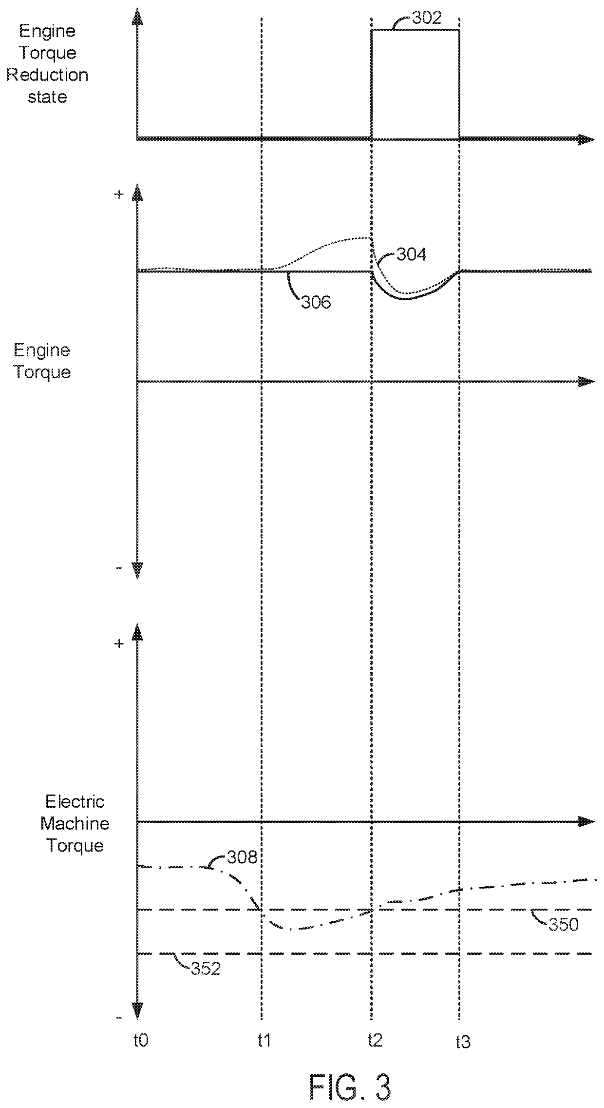
[0004]By reducing engine torque responsive to an error torque that is equal to the electric machine torque minus a minimum torque of the electric machine, it may be possible to provide the technical result of reducing the possibility of generating torque converter impeller speed flares. In particular, when torque of the electric machine approaches a minimum torque threshold, then engine torque may be reduced so that engine torque does not overcome electric machine torque. Consequently, speed of the driveline may be controlled to a requested speed even during conditions when the requested speed increases and the torque capacity of the electric machine may be reduced.
[0005]The present description may provide several advantages. In particular, the approach may improve driveline speed control. Further, the approach may prevent torque converter impeller speed flares. In addition, the approach may increase a life span of the electric machine by reducing a possibility of operating the electric machine near its capacity.

Problems solved by technology

However, if the engine is generating a greater torque than is requested due to modeling errors or other factors, torque converter impeller speed may flare (e.g., increase) more than is desired because the electric machine may have insufficient torque capacity to counteract the engine torque and control engine speed.
In addition, at higher speeds, torque production of the electric machine may be reduced, which may also make it difficult for the electric machine to maintain torque converter impeller speed at a requested or desired speed.
In particular, when torque of the electric machine approaches a minimum torque threshold, then engine torque may be reduced so that engine torque does not overcome electric machine torque.
In addition, the approach may increase a life span of the electric machine by reducing a possibility of operating the electric machine near its capacity.

Method used


Image

  • Methods and system for operating a driveline in a speed control mode
  • Methods and system for operating a driveline in a speed control mode
  • Methods and system for operating a driveline in a speed control mode

Examples


Embodiment Construction

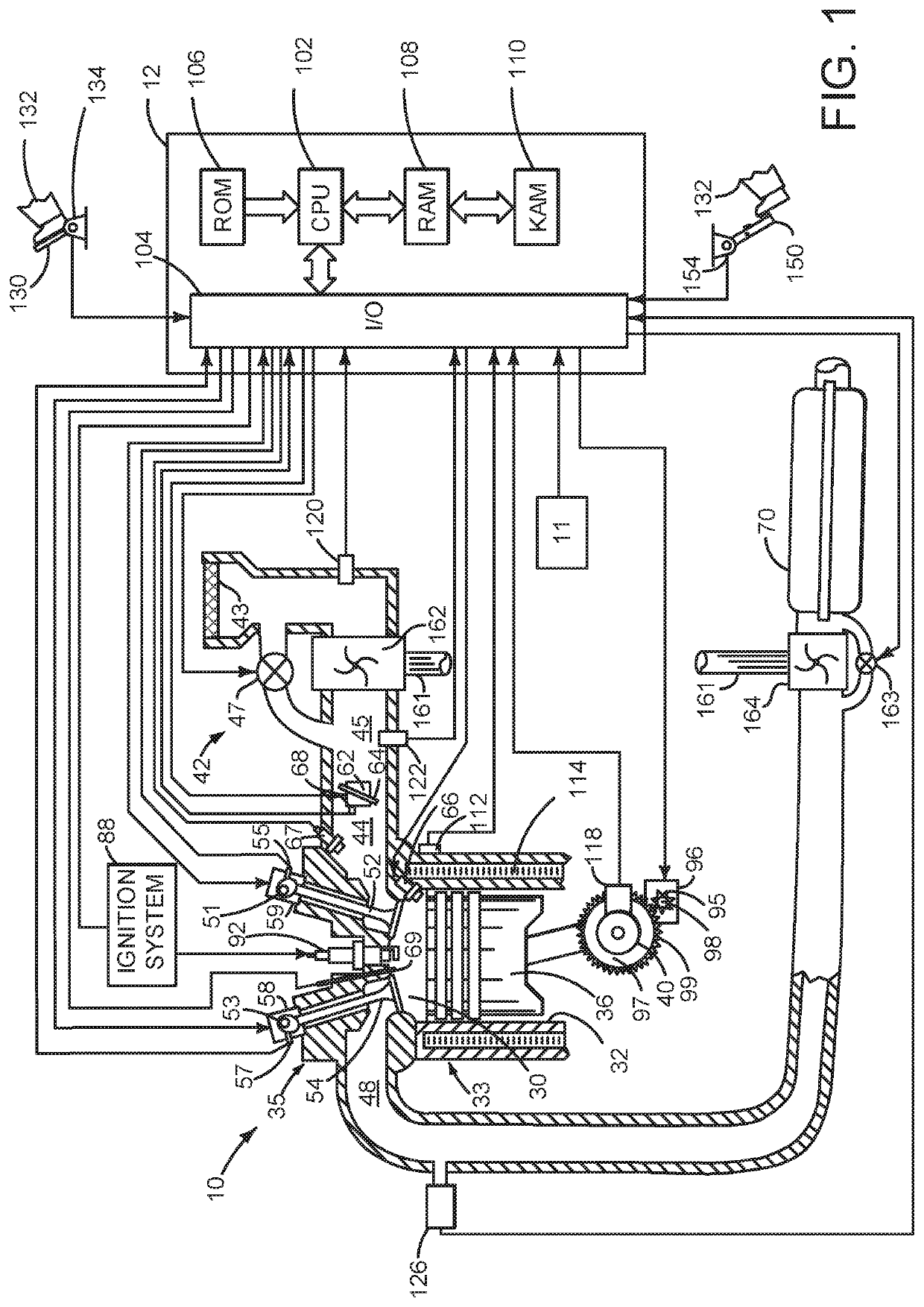
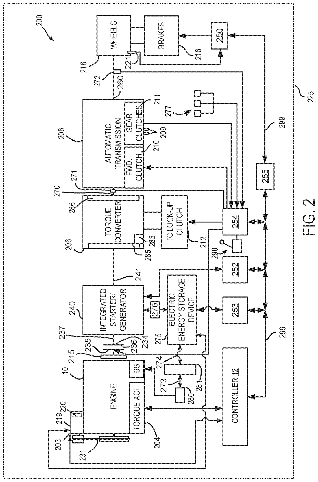
[0014]The present description is related to operating a driveline of a hybrid vehicle. The driveline may include an engine of the type shown in FIG. 1. The hybrid driveline may be configures as shown in FIG. 2. The hybrid vehicle driveline may be operated via a controller as shown in FIG. 3. The hybrid driveline may be operated via the methods of FIGS. 4 and 5.

[0015]Referring to FIG. 1, internal combustion engine 10, comprising a plurality of cylinders, one cylinder of which is shown in FIG. 1, is controlled by electronic engine controller 12. The controller 12 receives signals from the various sensors shown in FIGS. 1 and 2 and employs the actuators shown in FIGS. 1 and 2 to adjust engine and driveline operation based on the received signals and instructions stored in memory of controller 12.

[0016]Engine 10 is comprised of cylinder head 35 and block 33, which include combustion chamber 30 and cylinder walls 32. Piston 36 is positioned therein and reciprocates via a connection to cr...


PUM


Abstract

Systems and methods for operating a driveline of a hybrid vehicle are described. In one example, a torque of an engine is adjusted in response to an error between an actual electric machine torque and a minimum electric machine torque plus an offset torque. The reduction of engine torque may be performed when a driveline is operating in a speed control mode.

Description

FIELD[0001]The present description relates to methods and a system for operating a driveline of a hybrid vehicle.BACKGROUND AND SUMMARY[0002]An electric machine and an internal combustion engine may be included in a hybrid vehicle driveline to provide propulsive effort. The internal combustion engine may be have a higher maximum torque output capacity and a higher power output capacity than the electric machine, but the electric machine may respond to a request for additional or less torque more quickly than the engine. According to these characteristics, when both the engine and the electric machine are operating, the electric machine may be operated in a speed control mode (e.g., electric machine speed is adjusted to follow a requested or desired speed while electric machine torque is allowed to vary to meet the requested or desired speed) while at the same time the engine is operated in a torque control mode (e.g., engine torque is adjusted to follow a requested or desired torque...

Claims


Application Information

Patent Timeline
Patent Type & Authority Patents(United States)
IPC IPC(8): B60W20/10B60W10/08B60W30/18B60K6/387B60K6/40F02D33/00F02P5/15B60W10/06B60K6/24B60K6/26
CPCB60W20/10B60K6/387B60K6/40B60W10/06B60W10/08B60W30/18063F02D33/006F02P5/1502B60K6/24B60K6/26B60W2510/101B60W2710/0666B60W2710/081B60Y2200/92F02D2250/18B60W2710/083B60K6/48B60K2006/268B60K2006/4825B60W20/50B60W2510/083F02D29/02Y02T10/62Y02T10/70Y02T10/72
Inventor JOHRI, RAJITSYED, FAZAL
Owner FORD GLOBAL TECH LLC
Why Eureka
Eureka Blog
Learn More