
Shock absorber

a technology of shock absorber and seat, which is applied in the direction of shock absorbers, mechanical equipment, transportation and packaging, etc., can solve the problems of unavoidable seating noise, unavoidable seating noise, and inevitable seating nois

Active Publication Date: 2021-11-23
TOYOTA JIDOSHA KK
View PDF8 Cites 0 Cited by
  • Summary
  • Abstract
  • Description
  • Claims
  • Application Information

AI Technical Summary

Benefits of technology

[0009]The present disclosure provides a shock absorber of the spool valve type improved so that damping forces in the extension and compression strokes can be generated without generating seating noise by a single damping force generator supported by a piston.

Problems solved by technology

Therefore, when the shock absorber is activated and the reed valve is seated on the valve seat, a seating noise is inevitably generated.
Therefore, check valves must be provided, and since the check valves are reed valves, it is unavoidable that a seating noise is generated.
Even if the check valves are ball type check valves, a seating noise is unavoidably generated.
However, since two spool valves must be provided in the piston, a variable damping force shock absorber cannot be made with the structure described in Japanese translation of PCT international application No. 2013-507589.
As a result, a support structure of the actuator becomes complicated, and in some cases, a means to drive the actuator is required.

Method used


Image

  • Shock absorber
  • Shock absorber
  • Shock absorber

Examples


Embodiment Construction

[0061]The present disclosure will now be described in detail with reference to the accompanying drawings.

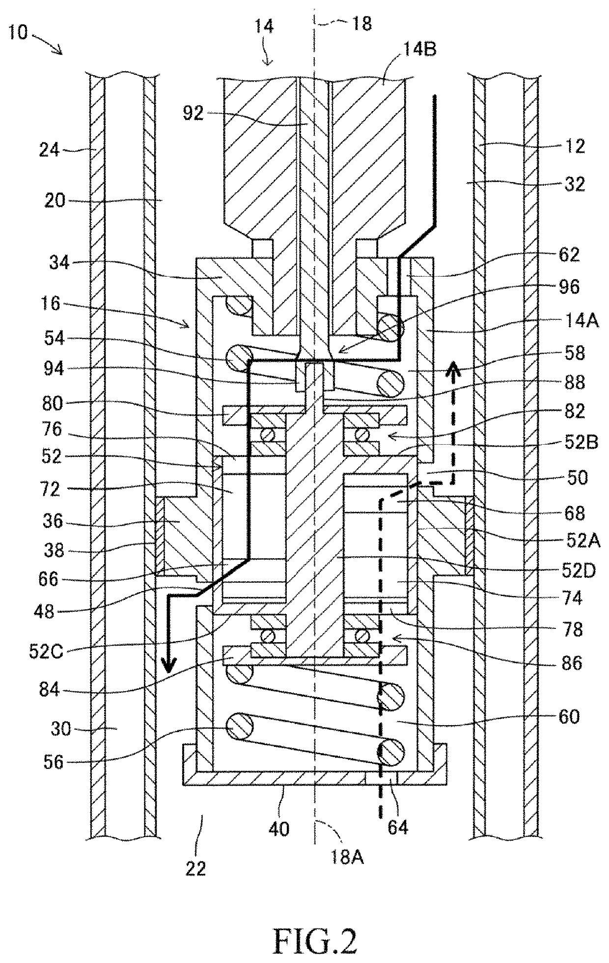
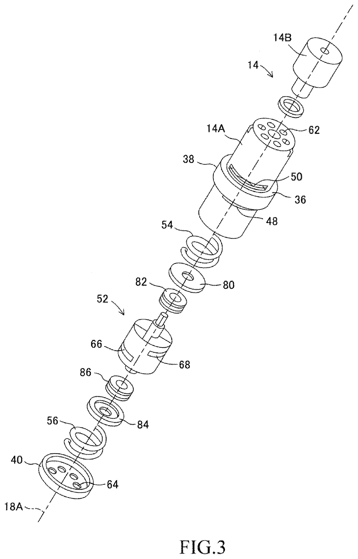
[0062]In FIG. 1, the shock absorber 10 of the embodiment includes a cylinder 12, a piston 14, and a damping force generator 16 supported by the piston within the cylinder. The piston 14 is reciprocally engaged with the cylinder 12 along a main axis 18 to form an upper cylinder chamber 20 as a first cylinder chamber and a lower cylinder chamber 22 as a second cylinder chamber in cooperation with the cylinder.

[0063]The shock absorber 10 is a twin-tube shock absorber, including an outer shell 24 that extends concentrically with the cylinder 12 along the main axis 18. Upper caps 26 and lower caps 28 are fixed at the upper and lower ends, respectively, of the cylinder 12 and outer shell 24. The upper cap 26 and the lower cap 28 work together with the cylinder 12 and the outer shell 24 to form an annular chamber 30.

[0064]The upper cylinder chamber 20, the lower cylinder chamber 22, and...


PUM


Abstract

A shock absorber has a damping force generator including a spool valve body that is reciprocally engaged with a cylindrical portion of a piston and pressed from both sides by a pair of compression coil springs. The cylindrical portion has first openings for extension and compression strokes, and the spool valve body has second openings for extension and compression strokes. When the piston is displaced relative to the cylinder, the spool valve body is displaced by a difference between pressures in upper and lower cylinder chambers, so that the damping force generator changes a degree of overlap of the first and second openings for the extension stroke in the extension stroke and a degree of overlap of the first and second openings for the compression stroke in the compression stroke.

Description

CROSS-REFERENCE TO RELATED APPLICATION[0001]This application claims priority to Japanese Patent Application No. JP2019-86355 filed on Apr. 26, 2019, the content of which is hereby incorporated by reference in its entirety into this application.BACKGROUND1. Technical Field[0002]The present disclosure relates to a shock absorber that has a damping force generator including a spool valve.2. Description of the Related Art[0003]General shock absorbers installed in vehicles such as automobiles include a cylinder, a piston that is reciprocally mated to the cylinder to form two cylinder chambers in cooperation with the cylinder, and a damping force generator installed in the piston within the cylinder. The damping force generator includes damping force generating valves for extension and compression strokes, and when the piston is displaced relative to the cylinder, oil flows between the two cylinder chambers through the damping force generating valves, and damping forces are generated by t...

Claims


Application Information

Patent Timeline
Patent Type & Authority Patents(United States)
IPC IPC(8): F16F9/512B60G17/08F16F9/34
CPCF16F9/5126B60G17/08F16F9/34F16F9/185F16F9/516F16F9/462F16F9/3405B60G13/08B60G2202/24
Inventor MIZUNO, KAZUYUKI
Owner TOYOTA JIDOSHA KK
Learn More