
Steering damper apparatus and damper apparatus

a technology of damper apparatus and damper, which is applied in the direction of steering device, cycle equipment, transportation and packaging, etc., can solve the problems of not being able to meet the various demands of the rider, and achieve the reduction of the performance required of the input torque selecting mechanism, the effect of reducing size and weight, and reducing cos

Inactive Publication Date: 2007-09-20
HONDA MOTOR CO LTD
View PDF7 Cites 23 Cited by
  • Summary
  • Abstract
  • Description
  • Claims
  • Application Information

AI Technical Summary

Benefits of technology

[0027] The present invention has the effect of generating a damping force of the damper only when there is an input from either the handlebar or the wheels and meeting to various steering characteristics desired by a rider, for example, when no damping force is applied to the manipulation of the handlebar or when information from a road surface is directly transmitted to the handlebar and, in addition, the rider wishes to obtain a sensation of the handlebar manipulation.
[0041] Furthermore, the present invention has the following effect. That is, by assembling the steering damper unit in the state where the neutral position in the rotating direction of the input and output shafts of the input torque selecting mechanism is determined, even when the steering shaft and the input torque selecting mechanism are disposed in a non-coaxial manner, it is possible to prevent a rotational phase difference (displacement of the neutral position) from occurring between the shaft and the input torque selecting mechanism.

Problems solved by technology

As a result, for example, when the damping force is not provided to the input from the handlebar, or when information from the road surface is directly transmitted to the handlebar, and, in addition, a rider wishes to obtain a sensation of the handlebar manipulation, it is not possible to meet various demands of the rider.

Method used


Image

  • Steering damper apparatus and damper apparatus
  • Steering damper apparatus and damper apparatus
  • Steering damper apparatus and damper apparatus

Examples


embodiment 1

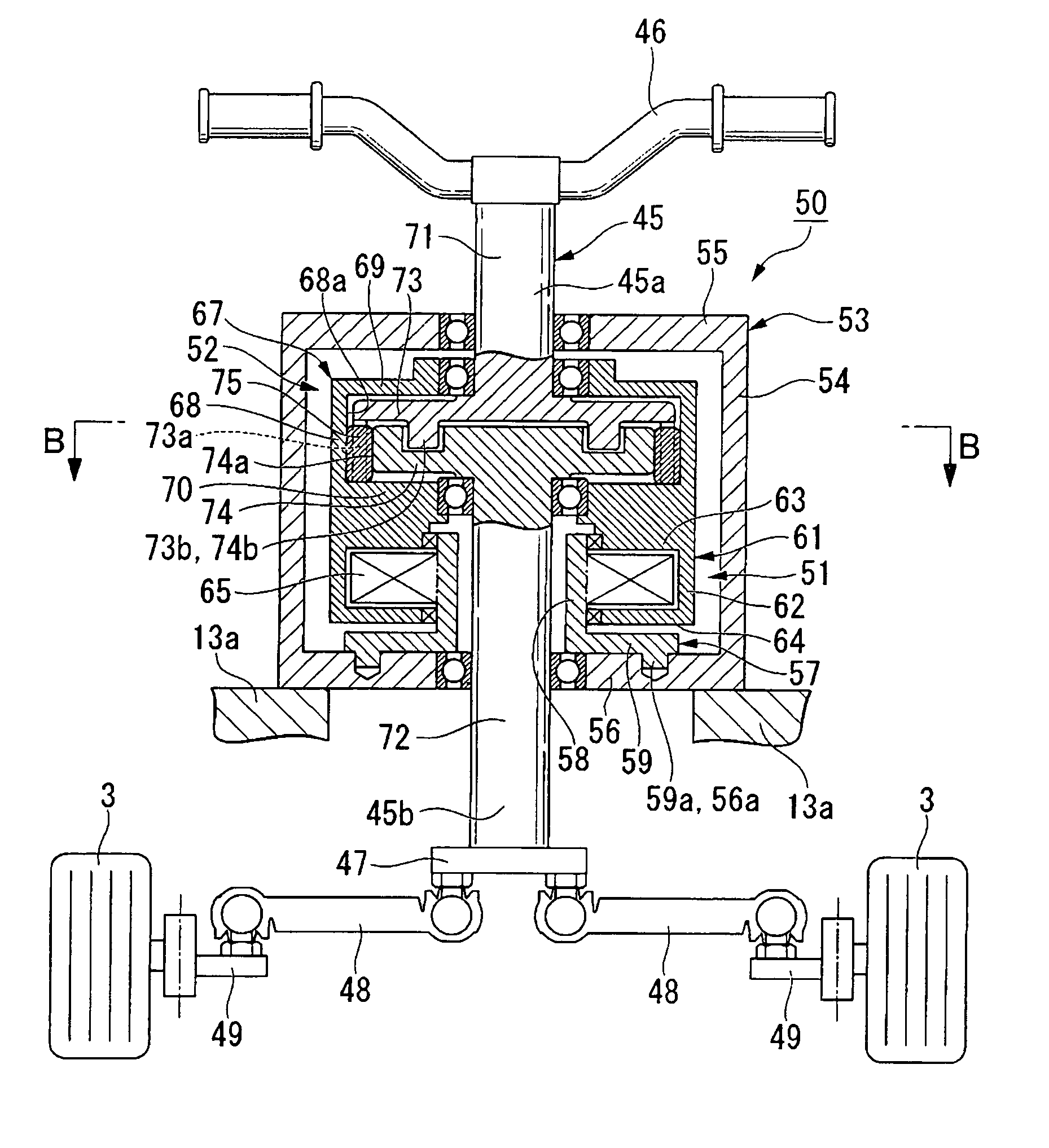
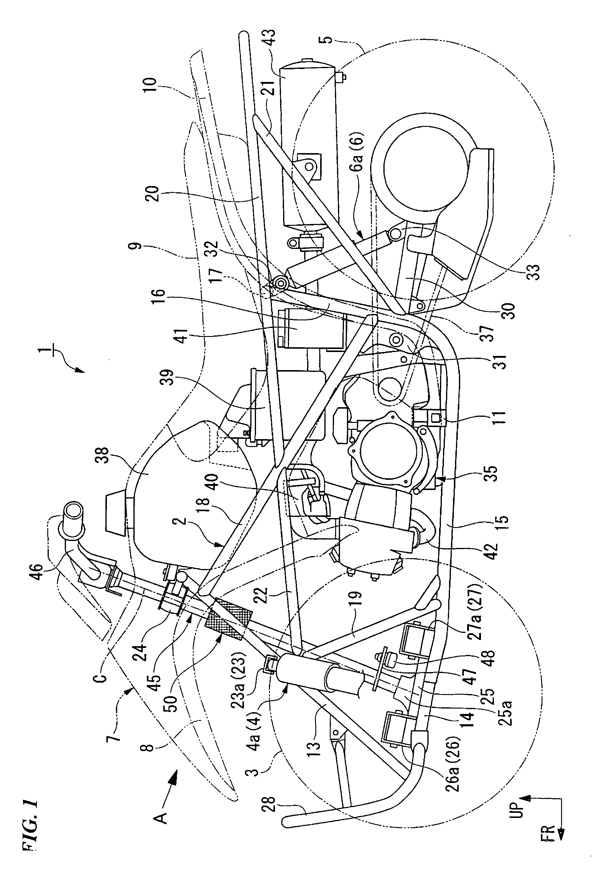
[0062] A saddle-ride type four-wheeled vehicle 1 as an all terrain vehicle is shown in FIG. 1. Left- and right-side front wheels 3 are suspended from the front part of a body frame 2 positioned at the middle in the vehicle width direction (the lateral direction) via an independent suspension type front suspension 4. Left- and right-side rear wheels 5 are suspended from the rear part of the body frame 2 via an axle suspension type rear suspension 6. The first half upper part of the body frame 2 is covered by a body cover 7. At both the left and right sides of the body cover 7 are mounted front fenders 8, respectively. At rear of the body frame 7 is disposed a seat 9. At both the left and right sides of the seat 9 are mounted rear fenders 10, respectively. Below the seat 9 is mounted a stepper 11, which protrudes to the left and right sides.

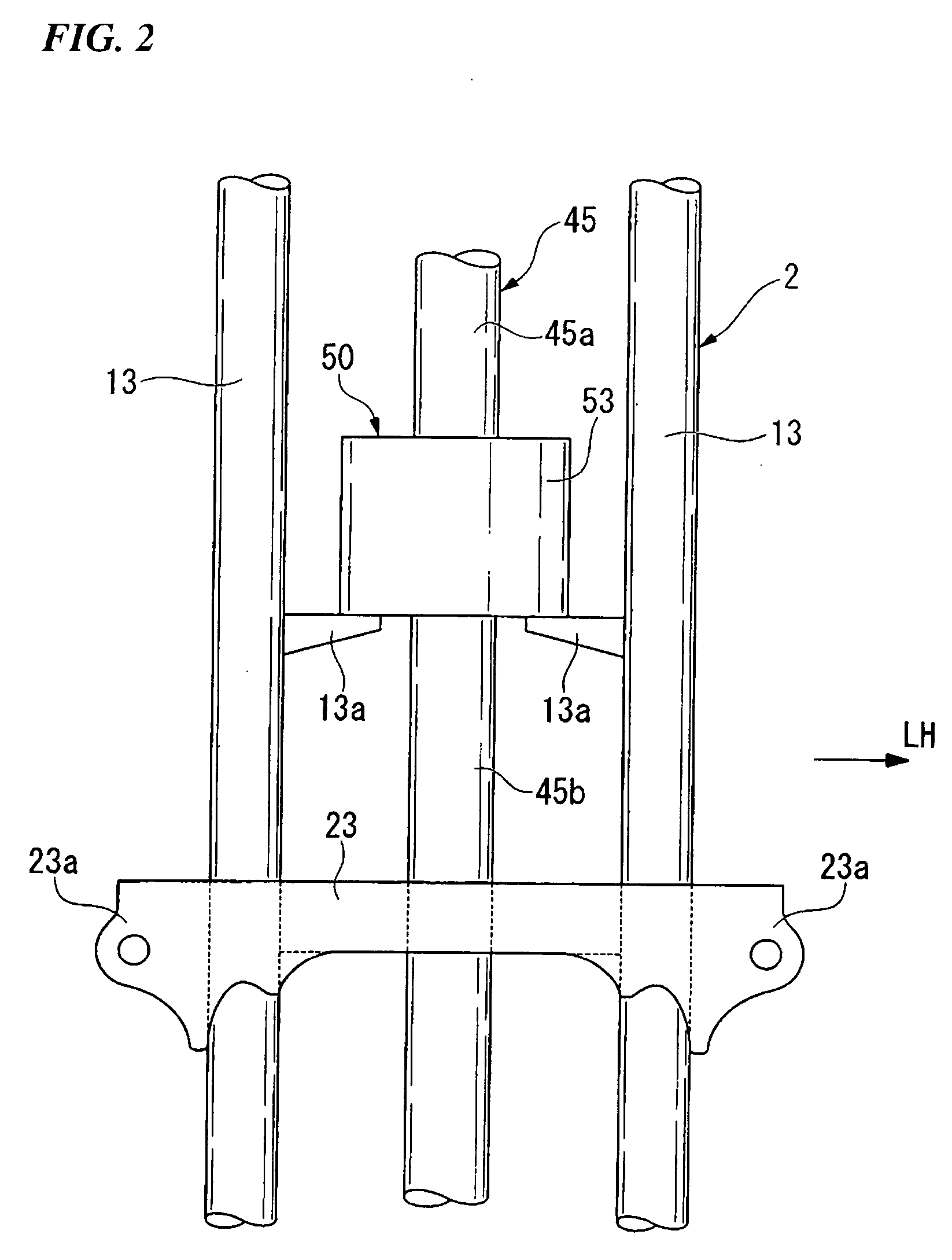
[0063] At the front part of the body frame 2 are disposed a pair of left- and right-side front pipes 13, which are inclined forward and rearward....

embodiment 2

[0102] Hereinafter, a second embodiment of the present invention will be described.

[0103] As shown in FIG. 5, a steering device according to this embodiment is principally different from the one according to the first embodiment in that the steering damper unit 50 is mounted upside down, and the input shaft 71 of the input torque selecting mechanism 52 is connected to the front wheel side while the output shaft 72 of the input torque selecting mechanism 52 is connected to the handlebar 46. Consequently, parts of this embodiment identical to those of the previous embodiment are denoted by the same reference symbols, and the description thereof will not be given.

[0104] The steering damper unit 50 according to this embodiment is constructed in a structure in which the damper 51 is disposed in the upper part of the outer case 53, and the input torque selecting mechanism 52 is disposed in the lower part of the outer case 53.

[0105] The input torque selecting mechanism 52 is constructed...

embodiment 3

[0114] Hereinafter, a third embodiment of the present invention will be described.

[0115] As shown in FIG. 6, a steering damper apparatus according to this embodiment is principally different from the ones according to the first and second embodiments in that a damper 151 and an input torque selecting mechanism 152 disposed in a non-coaxial manner, respectively, and the damper 151 and a housing 167 of the input torque selecting mechanism 152 are connected with each other via gears 157a and 167a. Consequently, parts of this embodiment identical to those of the previous embodiments are denoted by the same reference symbols, and the description thereof will not be given.

[0116] A steering damper unit 150 according to this embodiment is constructed in a structure in which the input torque selecting mechanism 152 is disposed in a space located coaxially with the steering shaft 45 in an outer case 153, and the damper 151 is disposed in a space offset from the steering shaft 45 in the oute...


PUM


Abstract

A steering damper apparatus includes: a body frame; wheels suspended by the body frame; a steering shaft rotatably supported by the body frame, one end of the steering shaft being connected to the wheel side; a handlebar connected to the other end of the steering shaft for rotating the steering shaft to steer the wheels; and a damper for damping the rotation of the steering shaft. The rotation of the steering shaft is damped by the damper only when there is an input from either the handlebar or the wheels.

Description

BACKGROUND OF THE INVENTION [0001] 1. Field of the Invention [0002] The present invention relates to a steering damper apparatus that generates a damping force in a steering system of a vehicle, and a damper apparatus that provides a damping force to input torque. [0003] This patent application claims priority on Japanese Patent Application No. 2006-037241 filed on Feb. 14, 2006, the disclosure of which is incorporated herein by reference. [0004] 2. Background Art [0005] In the past, there was a known steering damper apparatus constructed in a structure in which a damper is mounted in a steering system of a vehicle such that the rotation of the steering system caused due to the irregularity of a road surface can be damped by the damper (For example, see JP-A No. H07-165148). [0006] In the steering damper apparatus, however, the damper performs the damping operation equally irrespective of whether the force inputted to the steering system is the force from a handlebar or the force fr...

Claims


Application Information

Patent Timeline
Patent Type & Authority Applications(United States)
IPC IPC(8): B62D7/22F16D57/00B62K21/12
CPCB62D7/224B62K21/08Y10T464/50Y10T74/2078F16F9/12F16F15/10
Inventor WAKABAYASHI, TAKESHIMORI, YOTARO
Owner HONDA MOTOR CO LTD
Learn More