
System and method for determining the relative direction of an RF transmitter

a technology of relative direction and rf transmitter, which is applied in the field of electromagnetic absorption materials to achieve the effect of small antennas, small and cheaper

Active Publication Date: 2021-11-16
HISEP TECH
View PDF2 Cites 0 Cited by
  • Summary
  • Abstract
  • Description
  • Claims
  • Application Information

AI Technical Summary

Benefits of technology

The methods described in this patent are cheaper and smaller than previous techniques because they work directly on the RF signal, instead of using expensive receivers. This makes them more efficient and cost-effective.

Problems solved by technology

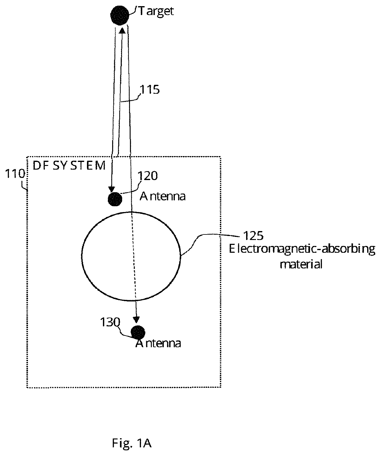
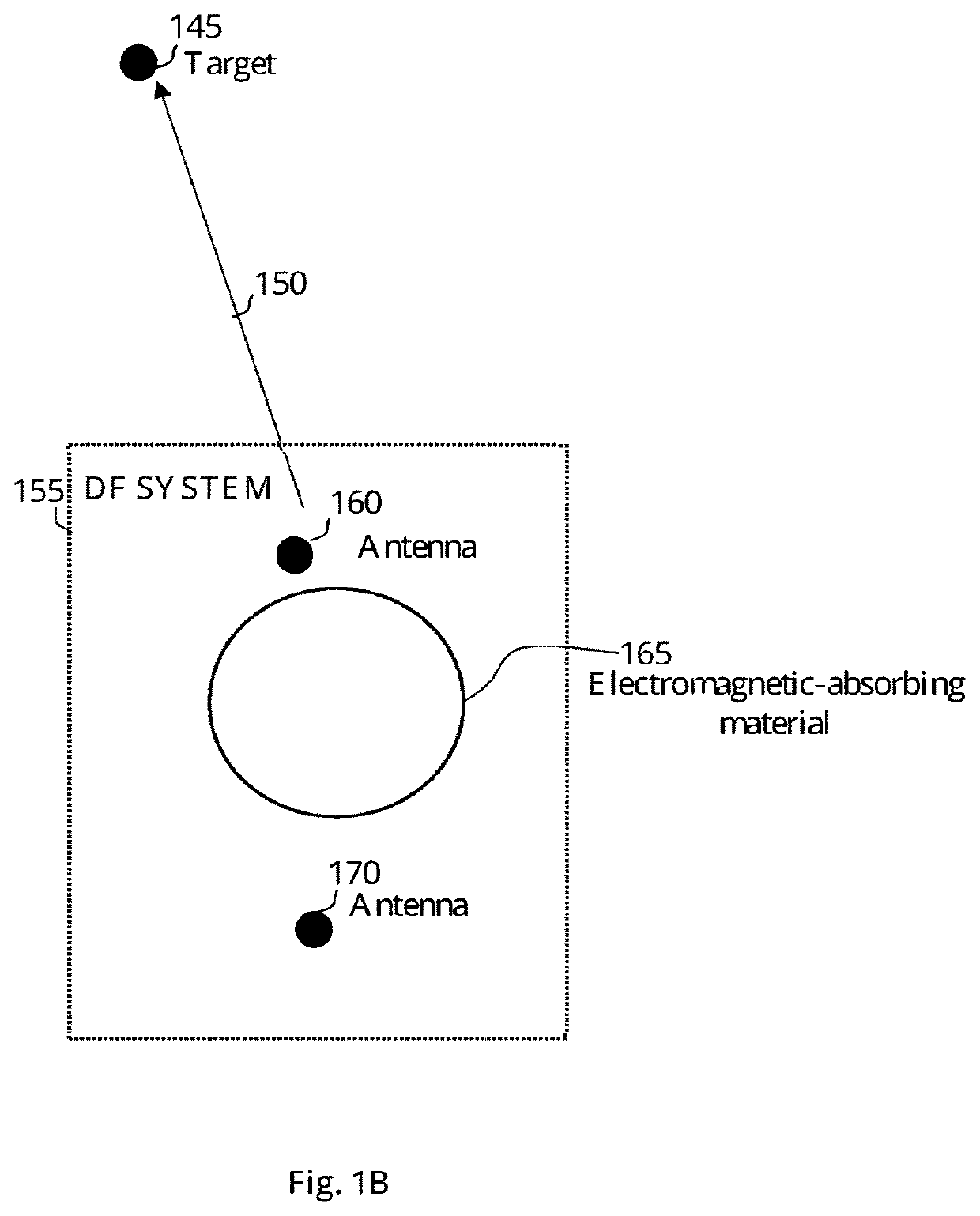
The RF signal absorption may result from the electromagnetic-absorbing material which may be associated with the DF system and obstruct at least some of the antennas from receiving the full strength of the RF signal.

Method used


Image

  • System and method for determining the relative direction of an RF transmitter
  • System and method for determining the relative direction of an RF transmitter
  • System and method for determining the relative direction of an RF transmitter

Examples


Embodiment Construction

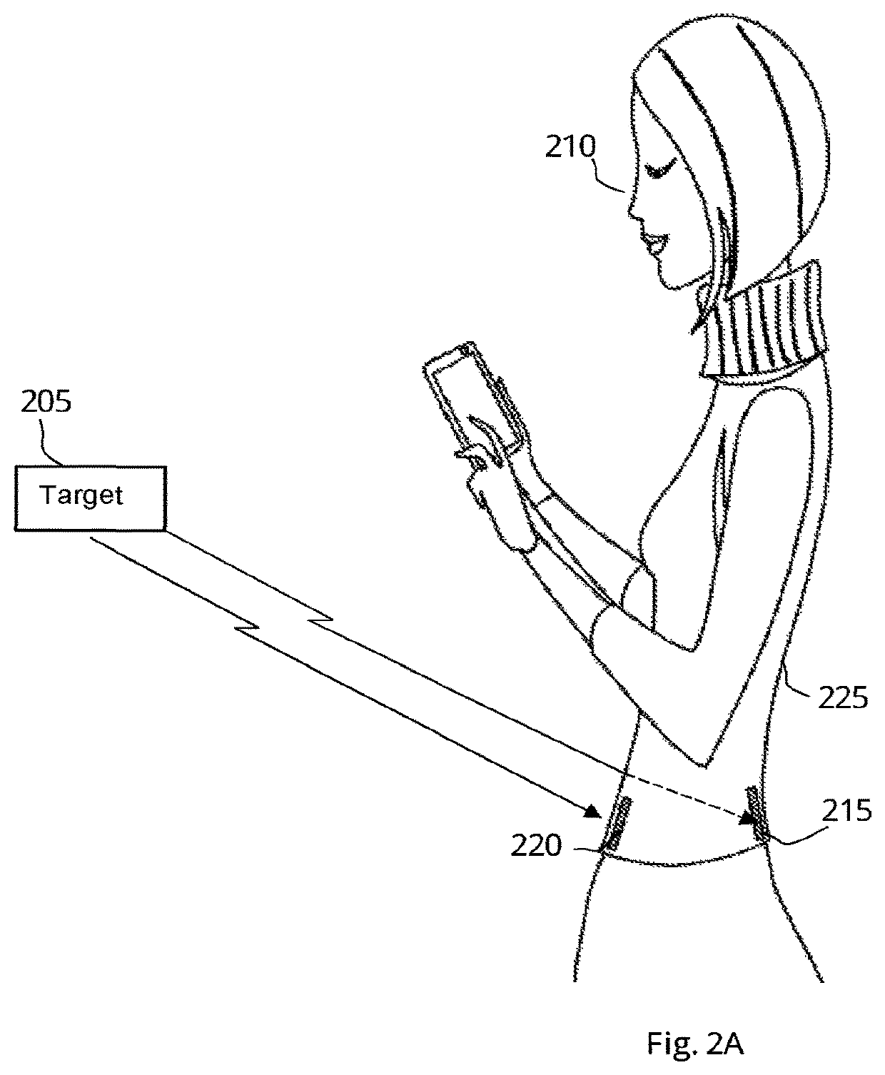
[0083]The present invention discloses a DF system and method to determine the relative direction of a target by utilizing electromagnetic-absorbing material and at least two antennas. The DF system comprises at least a pair of antennas designed to receive RF transmissions, a computerized unit configured to collect the RF signals received by the antennas and a memory unit to store the information received during the “relative direction determination” process. Such information may be directions of the targets, the number of targets, the absorption factor of the electromagnetic-absorbing material, the heading of the DF system, the alignment of the antennas versus each other and versus the absorbing material, and optionally additional information which may be related to the “relative direction determination” process. The DF system is designed to utilize a power source from an internal source such as a battery. In some cases, the DF system may be connected to an external power source suc...


PUM


Abstract

The subject matter discloses a method to determine a relative direction of a target RF transmitter, performed by a direction finding (DF) system comprising at least a pair of antennas having an electromagnetic-absorbing material between them, comprising conducting wireless communication between the target RF transmitter and each one of the antennas of the DF system, measuring the time of flight (TOF) of the target RF transmitter received at each antenna, calculating the difference between the TOFs measured at each one of the antennas in the pair, and determining a relative direction of the target RF transmitter based on the TOF required to reach each of the antennas.

Description

CROSS REFERENCE TO RELATED APPLICATIONS[0001]This application is a Continuation-in-Part of U.S. application Ser. No. 17 / 103,383 filed Nov. 24, 2021, which is a Continuation-in-Part of U.S. application Ser. No. 16 / 883,418 filed May 26, 2020 (now issued as U.S. Pat. No. 10,884,093), which is a Continuation of U.S. application Ser. No. 16 / 045,306 filed on Jul. 25, 2018 (now issued as U.S. Pat. No. 10,705,175), which is a Continuation of PCT / IL2017 / 050001 having International filing date of Jan. 1, 2017, which claims the benefit of priority of U.S. Provisional Application No. 62 / 286,987 filed on Jan. 26, 2016.[0002]This application also claims the benefit of priority of U.S. Provisional Application No. 63 / 152,854 filed Feb. 24, 2021.[0003]The contents of the above applications are all incorporated by reference as if fully set forth herein in their entirety.FIELD OF THE INVENTION[0004]The present invention relates to the use of wave absorbing material in general, and the use of electroma...

Claims


Application Information

Patent Timeline
Patent Type & Authority Patents(United States)
IPC IPC(8): G01S3/28G01S5/02G01S3/04
CPCG01S3/28G01S3/043G01S5/02G01S3/50G01S11/02G01S11/06
Inventor ERAD, YARIVVERED, GADERAD, MENACHEMVERED, URI
Owner HISEP TECH
Learn More