[0005]It is an objective of the present invention to provide a drill string component to form part of a drill string having a male end configured to withstand non-symmetrical loading forces acting on the drill string to reduce stress of the threaded section of the male end and minimise the risk of failure of the coupling. It is a further objective to provide a coupling that is resistant to bending waves in the drill string resultant for example from hole deviation or non-central strikes by the drive piston at the rearwardmost drill rod or shank adaptor. It is a further objective to provide a drilling component for shoulder contact coupling having a male threaded end that provides a secure coupling with a corresponding female threaded end of a neighbouring drill rod or other component of the drill string so as to form an integral and secure unit within the assembled drill string.
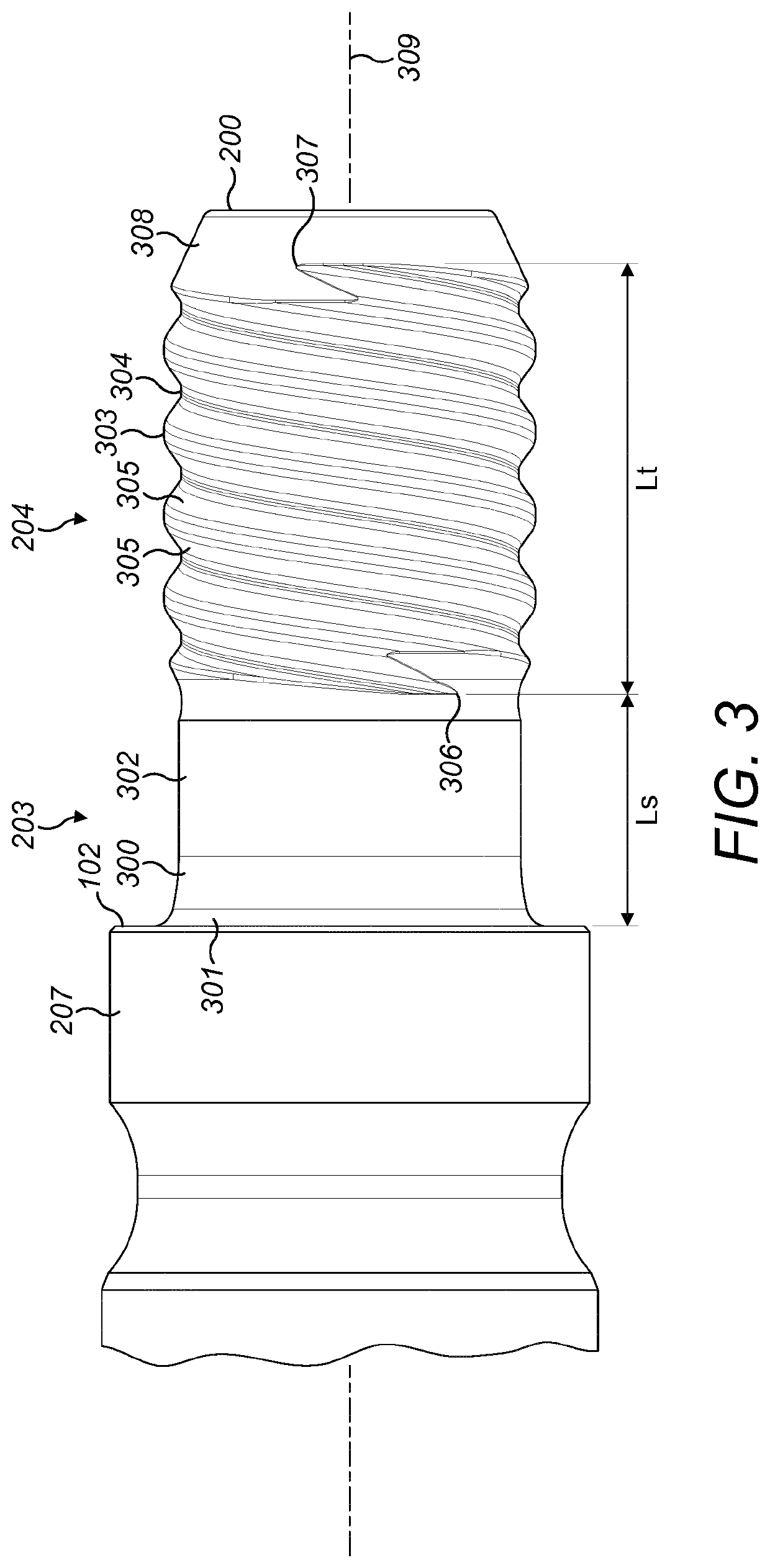
[0011]Optionally, the quotient Ls / Dy is in the range 0.4 to 1.0. Optionally the quotient Ls / Dy is in the range 0.45 to 1.0, 0.5 to 1.0, 0.55 to 1.0, 0.6 to 1.0, 0.65 to 1.0, 0.7 to 1.0, 0.75 to 1.0; 0.8 to 1.0 or 0.85 to 1.0. Preferably, the quotient Ls / Dy is in the range 0.4 to 0.8 or 0.5 to 0.8. Optionally, the quotient Ls / Dy may be equal to or greater than 0.45, 0.5, 0.6 or 0.7. Axially separating the helical threads from the shoulder contact region of the drill string component via this minimum axial length of the non-threaded shank minimises the magnitude of the bending forces transmitted through the helical thread resultant from lateral deviations in the position of the drill bit during drilling or potentially imperfect hammer strikes. Accordingly, the lifetime of the drill component is enhanced over conventional male couplings in addition to reducing the risk of down-the-hole coupling failures.
[0012]Preferably, the spigot comprises an axial length (L) defined between an axial endmost surface of the spigot and the side surface of the length section or shoulder, wherein the quotient Ls / L is equal to or greater than 0.25. More preferably, the quotient Ls / L is the range 0.25 to 0.5; 0.3 to 0.5; 0.35 to 0.5; 0.4 to 0.5; 0.45 to 0.5. By maximising the axial length of the non-threaded shank relative to the total axial length of the spigot, the threaded section is axially separated from the shoulder contact region of the component and hence is configured to better withstand bending moments and accordingly to reduce stress concentrations at the helical thread. Within this specification, the axially inner end of the threaded section is defined as the axial position at which a radial position of the crest or a root of the thread corresponds to the radial position of an external surface of the non-threaded shank.
[0013]Optionally, and to further enhanced the resistance to stress resultant from bending forces, the shank comprises a transitional region positioned adjacent the annular side surface wherein a cross sectional profile at the transition region in a plane extending in a longitudinal axis of the component is curved such that a cross sectional area of the shank increases axially towards the annular side surface. More preferably, the curvature of the transition region axially closest to the side surface comprises a first radius of curvature that is less than a second radius of curvature of the outer surface at the transition region axially closest the threaded section, the outside diameter of the transition region over the first and second radii of curvature increasing in a direction from the threaded section to the side surface. Accordingly, the axial junction between the shoulder region of the component and the spigot (and in particular the non-threaded shank) is reinforced against bending moments to reduce stress concentration and the risk of failure of the coupling under load. Reference to ‘curvature’ encompasses a smooth or gradual change in the surface profile and also a plurality of sequential linear increases in the diameter from the non-threaded shank to the shoulder that collectively may be regarded as a ‘curved’ shape profile.
[0017]Preferably, Ds is less than Dy. Preferably, Ds is less than a diametric distance (Di) between the radial positions of the roots (between the helical ridges) on diametrically opposed sides of the threaded section. More preferably, Ds may be in the range (Di minus Td) to (Di minus 4Td), where Td is the thread depth perpendicular to the longitudinal axis between the radial positions of a crest and a root. More preferably, Ds is in the range (Di minus Td) to (Di minus 3Td). Most preferably, Ds is equal to Di minus 2Td. The spigot, comprising a Ds configuration as detailed herein, is advantageous to allow optimisation of the transition region adjacent to the annular side surface of the shoulder or end of the main length section. In particular, a Ds that is less than Di enables an axially longer transition region and a greater radii of curvature at the transition between the non-threaded shank and the annular side surface (of the shoulder or main length section). Accordingly, the present configuration of Ds minimises stress concentrations at the base of the spigot (at its junction with the main length or shoulder section). The present configuration of Ds in combination with Ls is accordingly advantageous to provide a percussion component that is resistant to bending stresses and also configured to withstand the stresses resultant from transmission of the percussive shock wave through the spigot both when the components of the drill string are perfectly aligned axially and also when deflected (being aligned slightly transverse to one another) in use.
[0019]The subject invention is configured specifically as a threaded spigot for a percussion drill component. The elongate component and in particular the male spigot via a configuration of the threads and the non-threaded shank (as detailed herein) is adapted to withstand bending forces and stress concentrations resultant from transmission of the percussive shock whilst minimising any reduction in the magnitude of the shock wave during transmission. The thread profile of the spigot is adapted for percussion drilling and preferably the threads comprise a uniform diameter along the axial length of the threaded section Lt. That is, the threaded section is formed preferably as a generally cylindrical section. As such the thread profile is appreciably robust to withstand the shock wave transmission and hence high loading forces. In particular, the subject invention comprises a thread having a pitch length in the range 5 to 50 mm for drill components with increasing respective outside diameters. Additionally, a pitch angle of the thread of the subject invention may be in a range 5 to 10° for a component with a respective pitch length and outside diameter, where the pitch angle is the angle θ extending between the path of the helical thread path and the tangent perpendicular to the longitudinal axis of the elongate component. Additionally, the diameter Dy of the threaded section (the thread crest-to-crest distance) according to aspects of the present invention may be in a range 15 to 120 mm for respective pitch lengths and pitch angles. Accordingly, the subject invention may comprise a thread configuration in which the quotient of pitch length / thread diameter is in a range 0.3 to 0.6; 0.35 to 0.55 and optionally 0.4 to 0.46.
