System and method for installing and using graphical dies

a technology of die plate and die plate, applied in the field of graphics dies, can solve the problems of large die plate size, complicated installation process, and high cost of die plate, and achieve the effect of reducing the number of dies, and improving the quality of dies

Active Publication Date: 2021-10-19
METAL MAGIC INC
View PDF9 Cites 2 Cited by
  • Summary
  • Abstract
  • Description
  • Claims
  • Application Information

AI Technical Summary

Problems solved by technology

This type of machine typically has a small footprint with a lot of pressure.
Rotary presses tend to operate more quickly than clamshell presses, but typically the dies are more expensive and with longer set up times. As such, rotary presses are usually used for embossing projects when the necessary quantities needed to be produced justify the additional initial start-up expenses as compared with clamshell press embossing.
Moreover, a magnesium die can be destroyed with a single misfeed in the stamping machine.
These dies are among the most expensive as they require someone to hand sculpt the die based on image references provided (these images usually being transferred to the metal through a photo-etching acid bath for use as a template).
The process is quite fast, with the etching itself taking only a few minutes.
The disadvantage with magnesium is that it is soft.
Also, as mentioned previously, a single jam in a stamping press may permanently ruin a magnesium die.
The disadvantage with copper, like magnesium, is that because it is created using an etching process, it is most readily only usable for a single level emboss.
Depending on the complexity and detailing of the design, brass dies can be up to two or three times more expensive than copper dies.
Despite advances made over the years with installing and aligning graphical dies onto an embossing press, it still is frequently a time consuming and exacting process that has undesirable amounts of down time when dies are being switched out, repaired, aligned, and prepared for use.
Further, the '709 device still requires the ability to fine tune and movably adjust the die plates once the carrier plates are installed on the embossing press which, depending on how much adjustment is necessary, still would require an end users, especially less experienced users, to spend significant additional time adjusting and aligning the dies into proper register and final position.

Method used


Image

  • System and method for installing and using graphical dies
  • System and method for installing and using graphical dies
  • System and method for installing and using graphical dies

Examples


Embodiment Construction

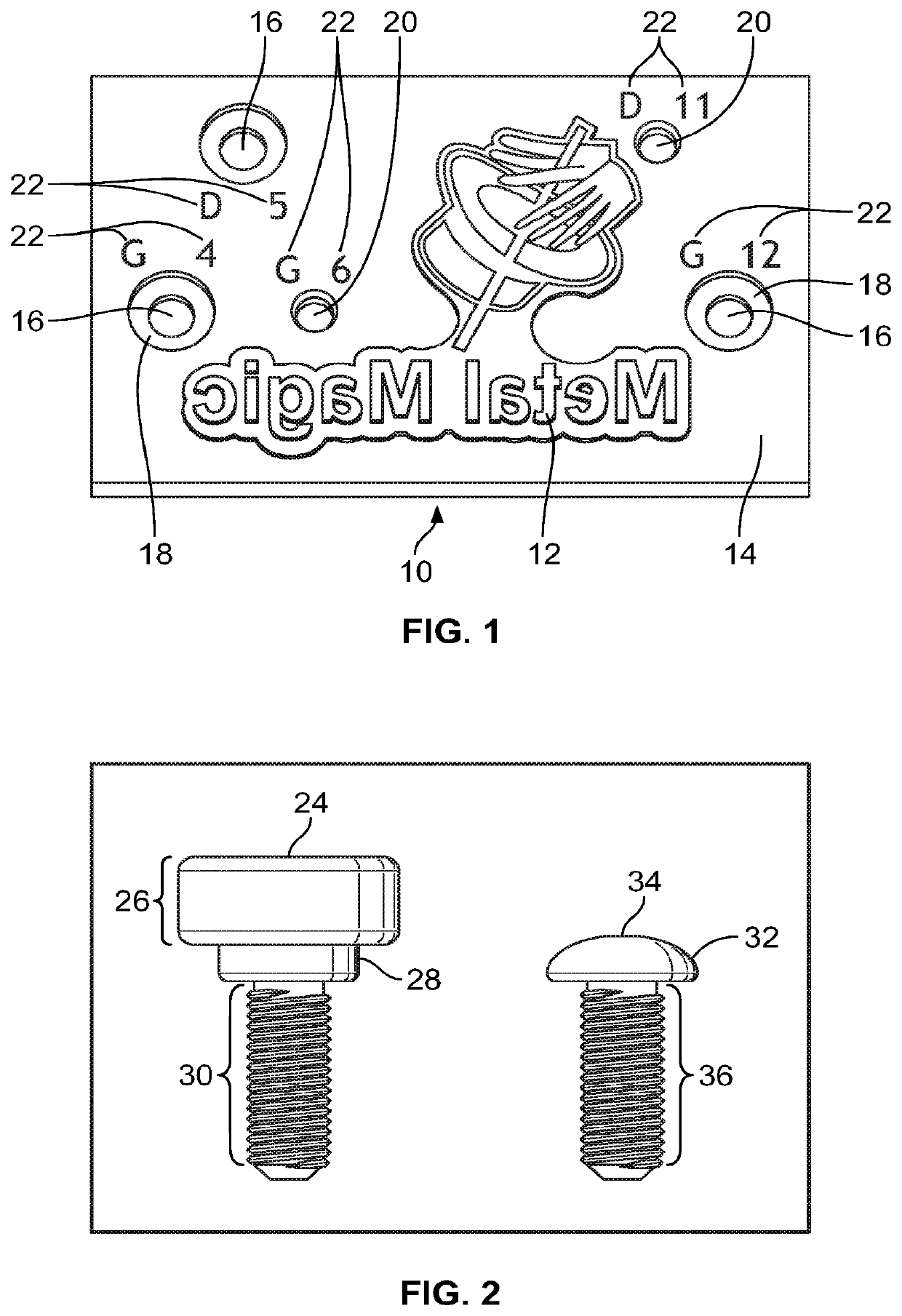
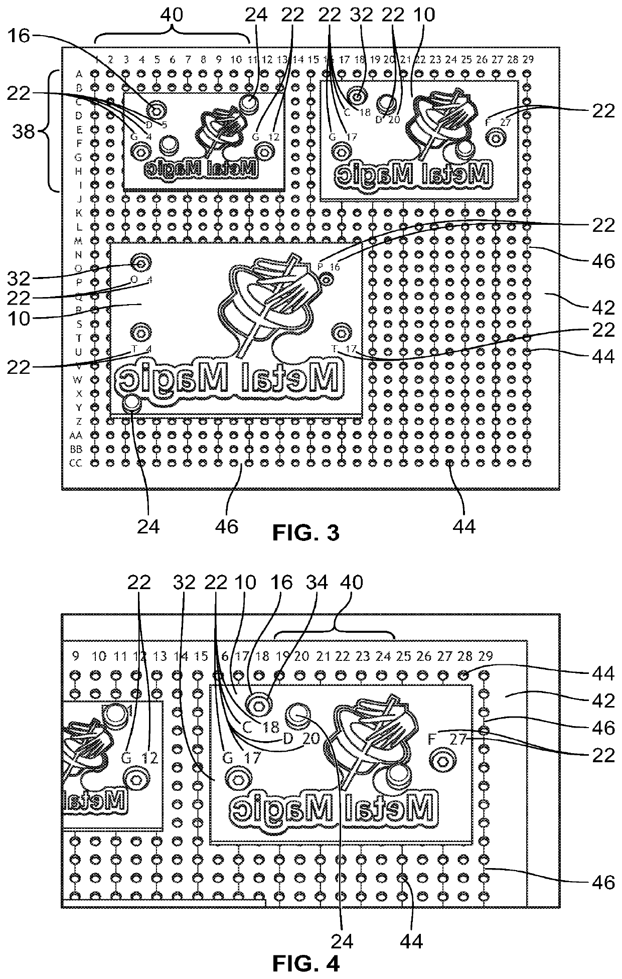
[0074]With reference to the figures and elements referenced therein, an improved system and method for aligning and installing graphical dies is provided. It should be appreciated that the embodiments described and shown herein are exemplary in nature only and that various additional embodiments are contemplated and within the scope of the present invention. For example, although the embodiments shown and described herein are directed towards a traditional flat embossing press, it should be appreciated that the present invention is readily adaptable for use with other press configurations, such as a rotary press. Additionally, although certain types of graphical dies may be shown and described herein for illustrative purposes, it should be appreciated that the system and method of the present invention is applicable no matter the type of graphical dies being used (i.e. embossing dies, debossing dies, foil stamping dies, etc.) With specific reference to FIGS. 3-4, the die system of t...


PUM


Abstract

A system and method for aligning and installing graphical dies onto an embossing press or foil stamping press is provided. The system includes a number of die support panels having a number of threaded openings disposed in columns and rows in a grid like fashion and identified with x and y axis indicia. The system also includes a number of dies with a number of apertures each identified with a pair of x and y axis indicia. Fasteners and indicia are used to align and attach the dies to the die support panels in a predetermined position. The system preferable further comprises one or more adjusters used to make minute positioning adjustments to the die after it is installed on the panel.

Description

CROSS-REFERENCE TO RELATED APPLICATION[0001]This application claims priority to, and the benefit of, U.S. Provisional Patent Application Ser. No. 62 / 574,353 filed on Oct. 19, 2017.FIELD OF THE INVENTION[0002]The present invention relates generally graphical dies for use with embossing or debossing paper stock. More particularly, the present invention relates to an improved system and method for aligning and installing die plates on a press.BACKGROUND OF THE INVENTION[0003]Embossing has been used in the field of graphical design as a finish for high end printed products for hundreds of years. Embossing is the process by which graphical dies are used to alter the surface of paper stock or other substrates by providing a three-dimensional or raised effect on selected areas. The procedure typically requires the use of two dies: one male die that is generally raised and one female die that is generally recessed. The engraved designs on the male and female dies fit into each other so that...

Claims


Application Information

Patent Timeline
Patent Type & Authority Patents(United States)
IPC IPC(8): B26D7/26B26F1/44B31F1/07B41F16/00B26F1/40
CPCB26D7/2614B26F1/40B26F1/44B31F1/07B26D2007/2607B26F2001/4418B31F2201/0702B41F16/0066B26D7/01B26D7/20B26D7/26B26F1/38B26F2001/4463
Inventor BROWN, CHARLESBROWN, CY R.
Owner METAL MAGIC INC
Why Eureka
Try Eureka