Apparatus and method for performing power calibration in wireless power transmission system

a technology of wireless power transmission and apparatus, applied in the direction of electrical apparatus, circuit arrangements, etc., can solve the problems of error between transmitted power and received power, different magnetic resonance methods, and error may be an obstacle to a sophisticated detection of foreign objects

Active Publication Date: 2021-10-05
LG ELECTRONICS INC
View PDF12 Cites 2 Cited by
  • Summary
  • Abstract
  • Description
  • Claims
  • Application Information

AI Technical Summary

Benefits of technology

[0031]It is possible to more sophisticatedly detect the foreign objects by calibrating the transmitted power and received power by adaptively reacting to the newly changed wireless charging environment and detecting the power loss based on the calibrated transmitted power and received power.

Problems solved by technology

However, the magnetic resonance method is different from the magnetic induction method in that energy is transmitted due to a concentration of magnetic fields on both a transmitting end and a receiving end, which is caused by the generated resonance.
However, an error may occur between the transmitted power and received power due to a change in the magnetic coupling according to the actual use environment (signal size, frequency, and duty cycle applied to the wireless power transfer system, distance / position alignment between Tx and the Rx, and the like) of Tx and Rx as well as unique physical characteristics of the wireless power transfer system.
The error may be an obstacle to a sophisticated detection of foreign object.

Method used


Image

  • Apparatus and method for performing power calibration in wireless power transmission system
  • Apparatus and method for performing power calibration in wireless power transmission system
  • Apparatus and method for performing power calibration in wireless power transmission system

Examples


Embodiment Construction

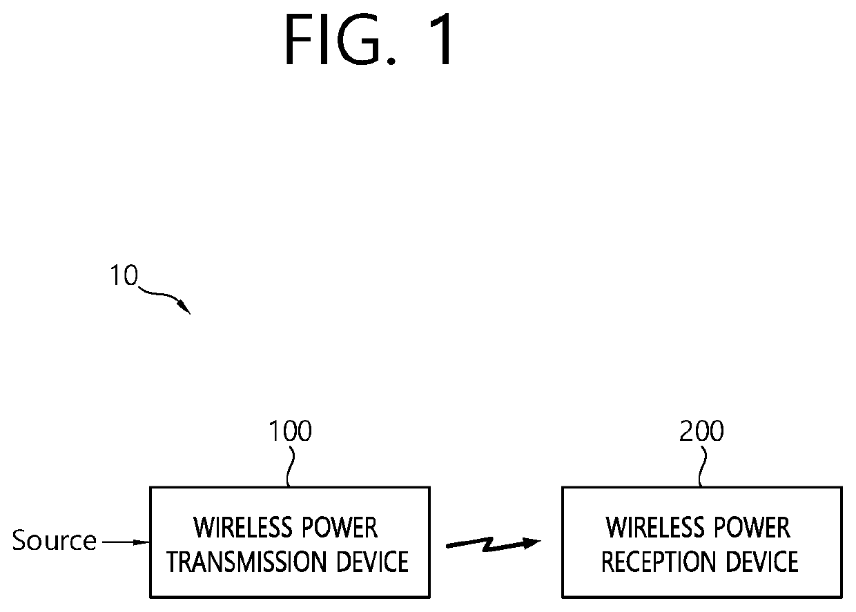
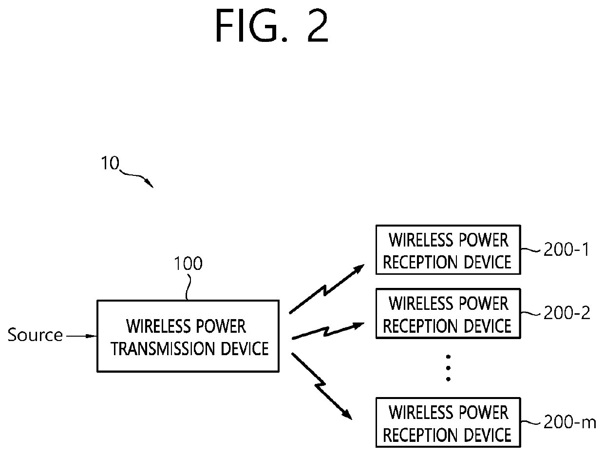
[0052]The term “wireless power”, which will hereinafter be used in this specification, will be used to refer to an arbitrary form of energy that is related to an electric field, a magnetic field, and an electromagnetic field, which is transferred (or transmitted) from a wireless power transmitter to a wireless power receiver without using any physical electromagnetic conductors. The wireless power may also be referred to as a wireless power signal, and this may refer to an oscillating magnetic flux that is enclosed by a primary coil and a secondary coil. For example, power conversion for wirelessly charging devices including mobile phones, cordless phones, iPods, MP3 players, headsets, and so on, within the system will be described in this specification. Generally, the basic principle of the wireless power transfer technique includes, for example, all of a method of transferring power by using magnetic coupling, a method of transferring power by using radio frequency (RF), a method ...


PUM


Abstract

The present invention relates to an apparatus and a method for performing power calibration in a wireless power transmission system. The present specification provides a wireless power transmission apparatus comprising: a power conversion unit configured to transmit, in a power transfer phase, wireless power generated on the basis of magnetic coupling to a wireless power receiving device; and a communication / control unit configured to perform an initial calibration for a power parameter prior to the power transfer phase, receive a first received power packet from the wireless power receiving device indicating the power received by the wireless power receiving device during the power transfer phase, and detect foreign matter by using the received power and a first power loss determined on the basis of the initial calibration. It is possible to adaptively respond to a newly changed wireless charging environment to calibrate transmission power and reception power, and it is possible to detect foreign matter more precisely by detecting a power loss on the basis of the calibrated transmission and reception power.

Description

CROSS-REFERENCE TO RELATED APPLICATIONS[0001]This application is the National Stage filing under 35 U.S.C. 371 of International Application No. PCT / KR2019 / 000251, filed on Jan. 8, 2019, which claims the benefit of U.S. Provisional Application Ser. No. 62 / 615,445, filed on Jan. 10, 2018, the contents of which are all hereby incorporated by reference herein in their entirety.TECHNICAL FIELD[0002]The present disclosure relates to wireless charging, and more particularly, to an apparatus and method for performing power calibration in a wireless power transfer system.BACKGROUND ART[0003]The wireless power transfer (or transmission) technology corresponds to a technology that can wirelessly transfer (or transmit) power between a power source and an electronic device. For example, by allowing the battery of a wireless device, such as a smartphone or a tablet PC, and so on, to be recharged by simply loading the wireless device on a wireless charging pad, the wireless power transfer techniqu...

Claims


Application Information

Patent Timeline
Patent Type & Authority Patents(United States)
IPC IPC(8): H02J50/80H02J50/12H02J50/40
CPCH02J50/80H02J50/12H02J50/40H02J50/60
Inventor PARK, YONGCHEOLPARK, JOONHOYOOK, GYUNGHWAN
Owner LG ELECTRONICS INC
Why Eureka
Try Eureka