


Quick Research
Generate reliable direction feasibility study reports for your R&D in just a few steps.

Technical Q&A
Discover and master advanced knowledge NOW. Basics, ideas, possibilities, all at once.

Find Solutions
As an expert in R&D theories, this can generate solutions to your technical problems instantly.

Evaluate Feasibility
Analyze your overall solution with one click, know your potential R&D risks in advance.

Monitor Landscape
Get weekly tech updates, stay abreast of the latest tech innovations and key insights.
Power over fiber system and data communication devices
a technology of data communication device and fiber system, applied in the direction of electromagnetic transceivers, optical elements, instruments, etc., can solve the problem of feed light leakage from a damage portion, and achieve the effect of higher energy
- Summary
- Abstract
- Description
- Claims
- Application Information
AI Technical Summary
Benefits of technology
Problems solved by technology
Method used
Image

Examples
first embodiment
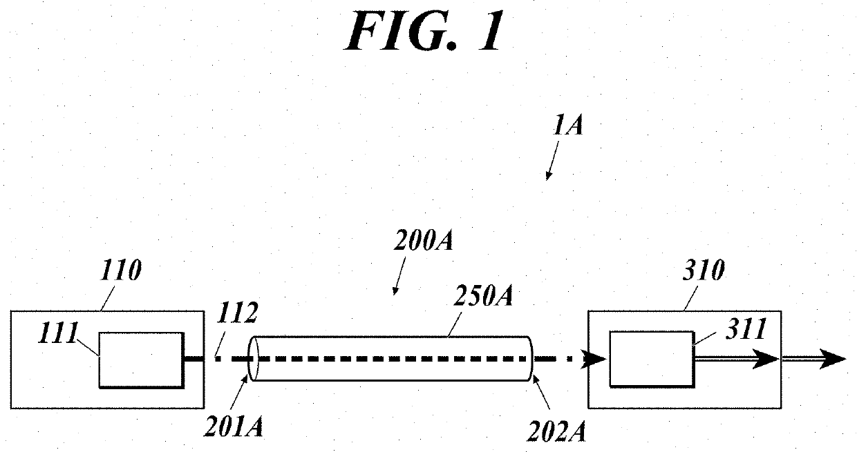
[0026]As shown in FIG. 1, a power over fiber (PoF) system 1A (optical power supply system) of this embodiment includes a power sourcing equipment (PSE) 110, an optical fiber cable 200A and a powered device (PD) 310.
[0027]In the present disclosure, a power sourcing equipment converts electric power into optical energy and supplies (sources) the optical energy, and a powered device receives (draws) the supplied optical energy and converts the optical energy into electric power.
[0028]The power sourcing equipment 110 includes a semiconductor laser 111 for power supply.
[0029]The optical fiber cable 200A includes an optical fiber 250A that forms a transmission path of feed light.
[0030]The powered device 310 includes a photoelectric conversion element 311.
[0031]The power sourcing equipment 110 is connected to a power source, and electrically drives the semiconductor laser 111 and so forth.
[0032]The semiconductor laser 111 oscillates with the electric power from the power source, thereby ou...
second embodiment
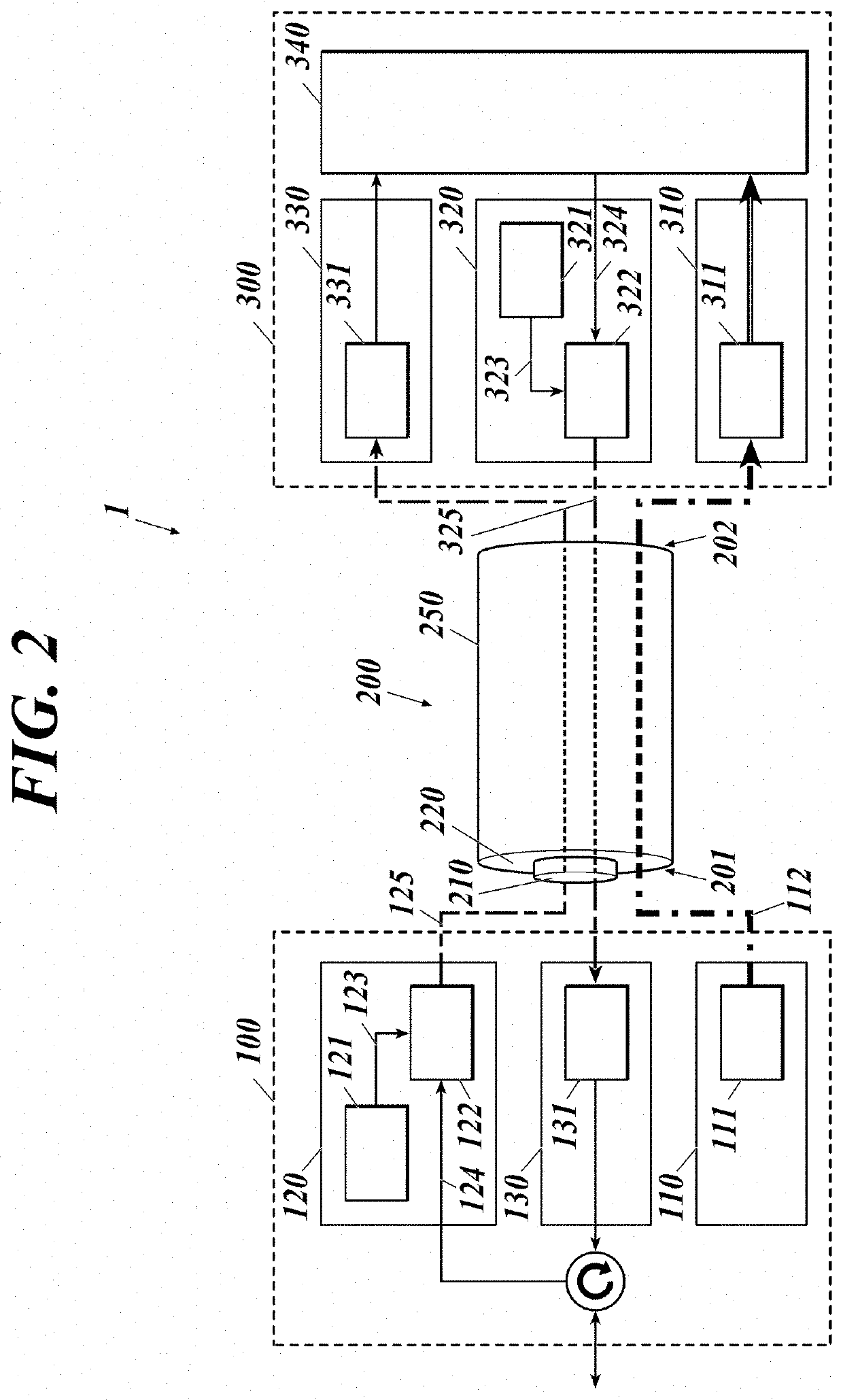
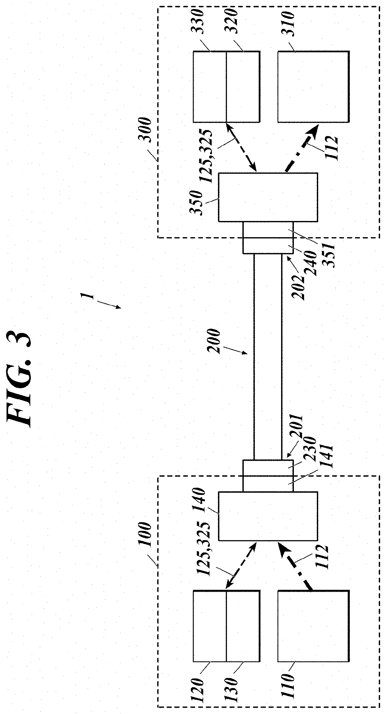
[0043]As shown in FIG. 2, a power over fiber (PoF) system 1 of this embodiment includes a power supply system through an optical fiber and an optical communication system therethrough, and includes: a first data communication device 100 including a power sourcing equipment (PSE) 110; an optical fiber cable 200; and a second data communication device 300 including a powered device (PD) 310.
[0044]The power sourcing equipment 110 includes a semiconductor laser 111 for power supply. The first data communication device 100 includes, in addition to the power sourcing equipment 110, a transmitter 120 and a receiver 130 for data communication. The first data communication device 100 corresponds to a data terminal equipment (DTE), a repeater or the like. The transmitter 120 includes a semiconductor laser 121 for signals and a modulator 122. The receiver 130 includes a photodiode 131 for signals.
[0045]The optical fiber cable 200 includes an optical fiber 250 including: a core 210 that forms a...
third embodiment
[0062]FIG. 5 is a block diagram of a power over fiber system according to a third embodiment to which the means for suppressing leakage of the feed light is applied. In FIG. 5, the same components as those described above are denoted by the same reference signs, and detailed descriptions thereof are omitted.
[0063]A power over fiber system 1C of the third embodiment includes an optical fiber 250C including a first transmission path 281 and a second transmission path 282 capable of transmitting light. The optical fiber 250C includes a core, a first cladding around the core and a second cladding around the first cladding. The optical fiber 250C may have more claddings, such as a third cladding located on the periphery of the second cladding and a fourth cladding located on the periphery of the third cladding. Two of the core and the claddings are used as the first transmission path 281 and the second transmission path 282. The feed light 112 is transmitted through the first transmissio...
PUM
 Abstract
Description
Claims
Application Information
 - R&D Engineer
- R&D Manager
- IP Professional
- Industry Leading Data Capabilities
- Powerful AI technology
- Patent DNA Extraction
Browse by: Latest US Patents, China's latest patents, Technical Efficacy Thesaurus, Application Domain, Technology Topic, Popular Technical Reports.
© 2024 PatSnap. All rights reserved.Legal|Privacy policy|Modern Slavery Act Transparency Statement|Sitemap|About US| Contact US: help@patsnap.com