
Heat exchanger device for EGR systems

a heat exchanger and egr technology, applied in the direction of heat exchange apparatus safety devices, machines/engines, light and heating apparatus, etc., can solve the problems of current heat exchangers, high exhaust gas temperature, dilatations with subsequent stresses, etc., and achieve the effect of reducing thermal fatigu

Active Publication Date: 2021-09-28
BORGWARNER EMISSIONS SYST SPAIN S L U
View PDF13 Cites 0 Cited by
  • Summary
  • Abstract
  • Description
  • Claims
  • Application Information

AI Technical Summary

Benefits of technology

The present invention provides a cooling system for a tube bundle. The system has a separator that separates a hot area from a cold area, with communication windows allowing the coolant to flow between the areas. This cooling system has the benefits of creating a more uniform temperature distribution and reducing bubble formation. In addition, the system has a small separation between the separator and the second baffle to prevent thermal fatigue. Overall, the cooling system improves the efficiency and stability of the cooling process.

Problems solved by technology

Likewise, the high-performance requirements for internal combustion engines call for operating at high temperatures which give rise to very high exhaust gas temperatures in the inlet of the heat exchanger.
The reduction of heat transfer from the hot gas to the liquid coolant causes the temperature of the transfer surface to rise suddenly close to the temperature of the hot gas instead of being close to the temperature of the liquid coolant, giving rise to dilatations with its subsequent stresses and damage to the material.
Even with these precautions, current heat exchangers present various problems that are identified below.
The first problem is the existence of stagnation regions close to the hot baffle, the baffle associated with the end through which hot gas enters the tube bundle.
The low speeds, and particularly the stagnation regions, do not remove the liquid coolant the temperature of which gradually increases due to the heat of the exchange surface.
Furthermore, once boiling is reached, since it is a stagnation region, there are also no means for removing the generated vapor.
The second identified problem is the removal of the bubbles generated during boiling.
These bubbles tend to accumulate and if the region where they accumulate is also extensive, then they cannot be evacuated and will increase the problem of establishing areas in direct contact with the gas which reduce the heat transfer rate due to the effect of the generated vapor layer.

Method used


Image

  • Heat exchanger device for EGR systems
  • Heat exchanger device for EGR systems
  • Heat exchanger device for EGR systems

Examples


first embodiment

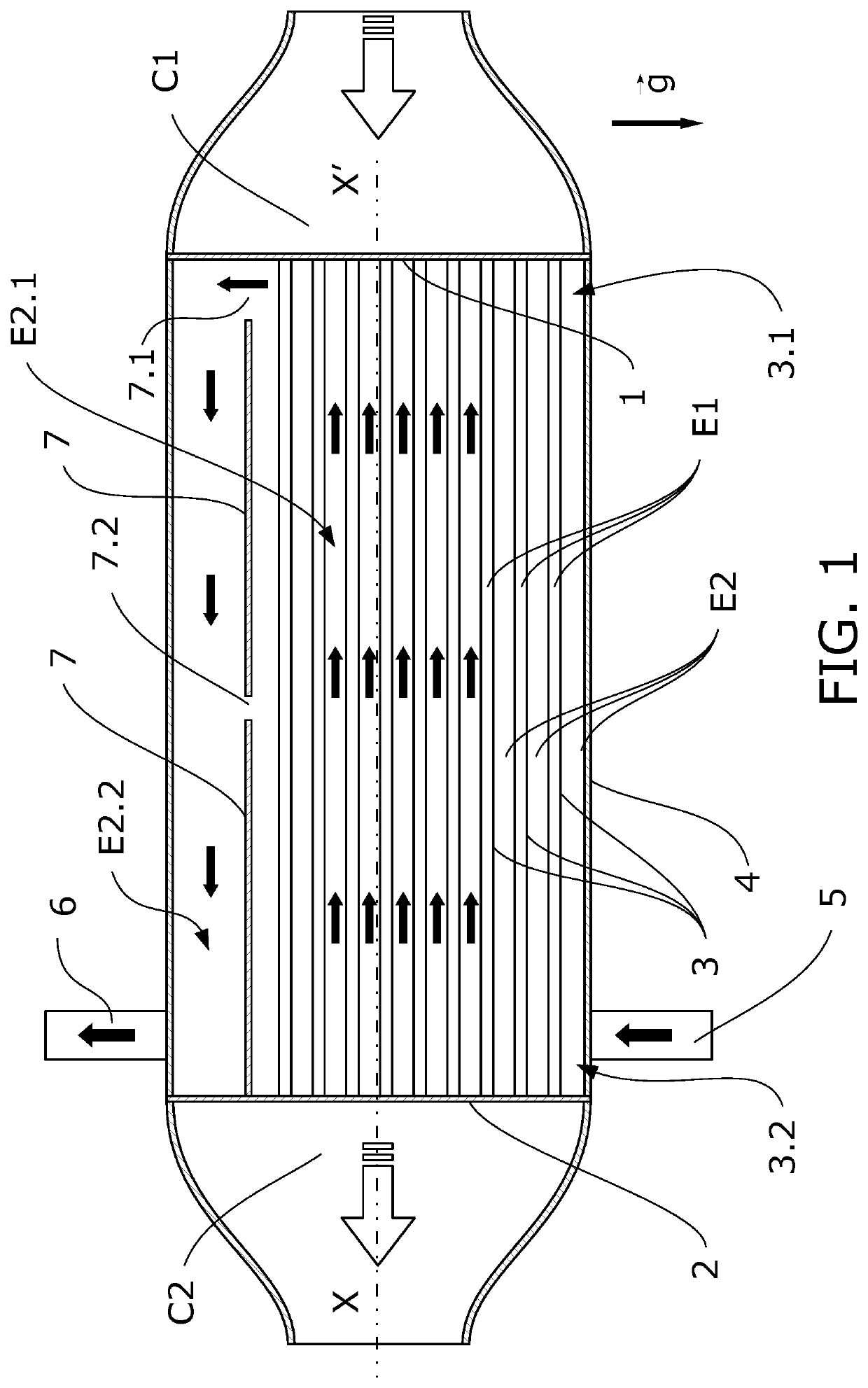
[0069]FIG. 1 is a schematic figure of the invention depicting a longitudinal section of the heat exchanger according to this first example.

[0070]The heat exchanger comprises a hot gas inlet, wherein in this embodiment the inlet is configured by means of an inlet manifold (C1) located on the right-hand side of the drawing. The flow of the hot gas is depicted by a large, hollow arrow. According to other embodiments, the coupling of the heat exchanger with other devices located upstream of the gas flow, such as a filter or a catalytic converter, can be direct coupling without using a manifold.

[0071]After traversing the heat exchanger giving off part of its heat, the cooled gas exits through an outlet manifold (C2) located on the left-hand side of the same drawing. The flow of the cooled gas is also depicted with a large, hollow arrow. Likewise, according to other embodiments the coupling with other elements located downstream of the gas flow can be direct coupling without using a manif...

third embodiment

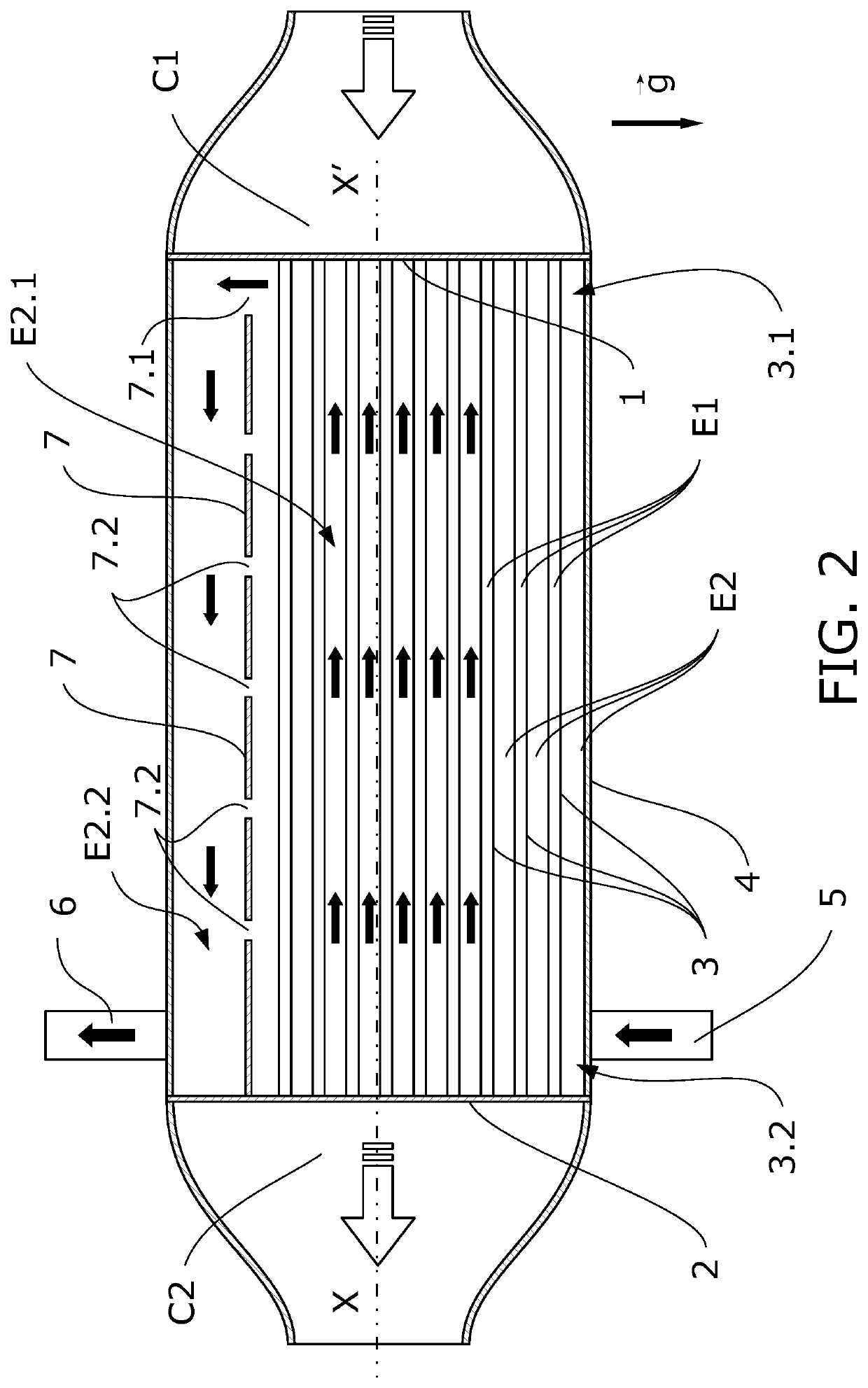
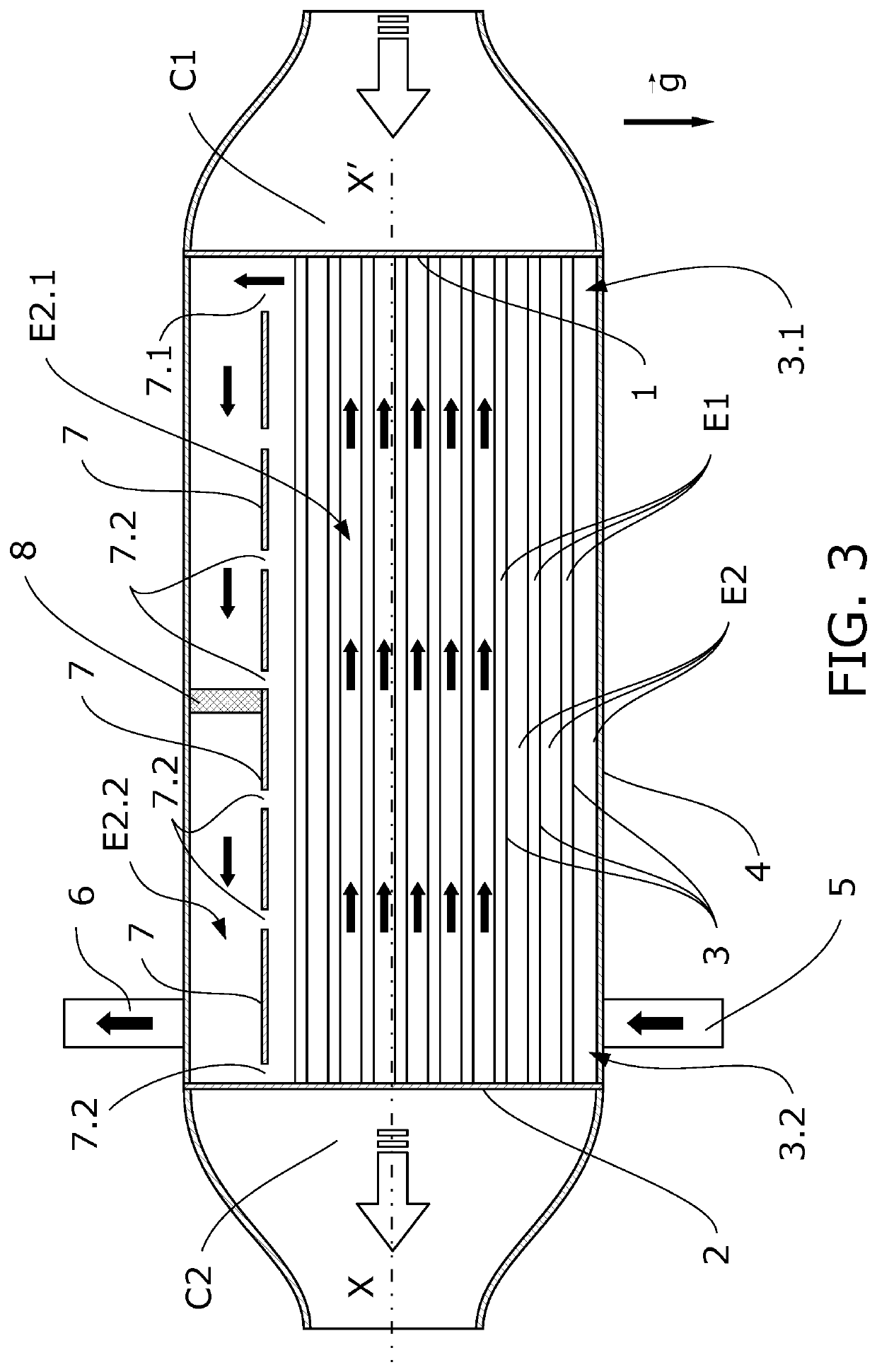
[0103]There is a possibility that a stagnation area may appear in the second degassing sub-space (E2.2), at its end in contact with the second outlet port (6). FIG. 3 shows a third embodiment in which an additional opening (7.2) has been added by means of distancing the separator (7) and the second baffle (2), allowing the passage of a small liquid coolant flow intended for preventing the appearance of stagnation or recirculation areas.

[0104]The same FIG. 3 is used to describe another embodiment which allows breaking the vapor bubbles before they exit the heat exchanger and which is applicable to any of the examples described up until now and below.

[0105]According to this embodiment, the second sub-space (E2.2) houses a porous element (8) which, although it allows the passage of the liquid coolant, forms narrow channels that either cause gas bubbles to break into other smaller bubbles or even to collapse, causing them to disappear.

[0106]The porous element (8) preferably covers the e...

fourth embodiment

[0114]FIG. 4 schematically shows a cross-section in which said cross-section is located close to the first baffle (1) to enable observing the inner spaces and the second baffle (2) where the inlet port (1) and the outlet port (2) are located.

[0115]This section does not allow observing the main opening (7.1) allowing the passage of the liquid coolant from the first exchange sub-space (E2.1) to the second degassing sub-space (E2.2) as it corresponds to the section that is eliminated to enable observing the inside of the heat exchanger.

[0116]This embodiment uses a shell (4) having a circular section and the separator (7) is formed by a bent sheet defining a first heat exchange sub-space (E2.1) in the lower part and a second degassing sub-space (E2.2) in the upper part. In this embodiment, the tubes of the tube bundle (3) are planar tubes vertically oriented to favor the upward movement of the bubbles generated on the exchange surfaces, being removed from the space between tubes (3) wh...


PUM


Abstract

The present invention relates to a heat exchanger device for EGR (“Exhaust Gas Recirculation”) systems, with a constructive solution which minimizes thermal fatigue when boiling occurs. The invention is characterized by a specific configuration of the inner space of the shell divided into a first exchange sub-space and a second degassing space communicated with one another, and wherein the inlet and outlet ports are located at the end where the cold baffle is located.

Description

CROSS-REFERENCE TO RELATED APPLICATIONS[0001]The present application claims priority to European Patent Application Serial No. EP19383062.7, filed Nov. 29, 2019, the disclosure of which is hereby incorporated herein by reference.OBJECT OF THE INVENTION[0002]The present invention relates to a heat exchanger device for EGR (“Exhaust Gas Recirculation”) systems, with a constructive solution which minimizes thermal fatigue when boiling occurs.[0003]The invention is characterized by a specific configuration of the inner space of the shell divided into a first exchange sub-space and a second degassing space communicated with one another, and wherein the inlet and outlet ports are located at the end where the cold baffle is located.BACKGROUND OF THE INVENTION[0004]One of the fields of the art with the most intensive development is the field of heat exchangers intended for EGR systems in internal combustion engines, in which space requirements in the engine compartment call for the device t...

Claims


Application Information

Patent Timeline
Patent Type & Authority Patents(United States)
IPC IPC(8): F02M26/32
CPCF02M26/32F28D7/16F28D7/1607F28F9/005F28F9/22F28F2009/224F28F2265/18F02M26/29
Inventor CARRERA GARCÍA, JULIO ABRAHAMDÍAZ BÓVEDA, CLARAPÉREZ RODRÍGUEZ, JOSÉ MANUELSIMÓ CARDALDA, GONZALOLÓPEZ FERREIRO, FELIXMENDEZ CALVO, MARIA ISABELFERNÁNDEZ VILLANUEVA, JUAN LUISPRIETO, RODOLFO
Owner BORGWARNER EMISSIONS SYST SPAIN S L U
Learn More