
Evaporation apparatus for treating waste water

a technology of evaporation apparatus and waste water, which is applied in the direction of contaminated groundwater/leachate treatment, vortex flow apparatus, filtration, etc., can solve the problems of high cost of sacrificial electrodes, high cost of transportation of produced water, and large amount of water injected in hydraulic fracturing processes, etc., to achieve low cost, low maintenance, and safe

Active Publication Date: 2021-09-21
ABTECH IND
View PDF25 Cites 3 Cited by
  • Summary
  • Abstract
  • Description
  • Claims
  • Application Information

AI Technical Summary

Benefits of technology

This approach achieves a reduction of up to 99% in water volume, producing steam that meets regulatory standards, is cost-effective, safe, and requires minimal maintenance, with the ability to operate on-site, thereby minimizing transportation needs.

Problems solved by technology

In particular, hydraulic fracturing processes require a significant amount of injected water, a large portion of which flows back as produced water.
This method usually involves expensive transportation of produced water from the production site to the injection site.
However, those methods often rely on sacrificial electrodes that are costly.
Moreover, any change in the constitution of the produced water, which is typical in the oil and gas industry, requires re-calibration of the apparatus.
Membrane treatment methods also result in reusable water, but are expensive and require significant maintenance.
None of the foregoing methods are believed to address issues related to transport of the treated water.
Heat transfer to the produced water using this method is less efficient than introducing the produced water directly to the heat source, and the apparatus requires significant maintenance.
The impurities in produced water prove challenging for treatment processes, as they are prone to cause clogging and corrosion of expensive, high-maintenance machinery, or the methods of achieving quality standards are complicated, difficult, or impossible to achieve.
Nevertheless, transporting and disposing of produced water results in significant expense.

Method used


Image

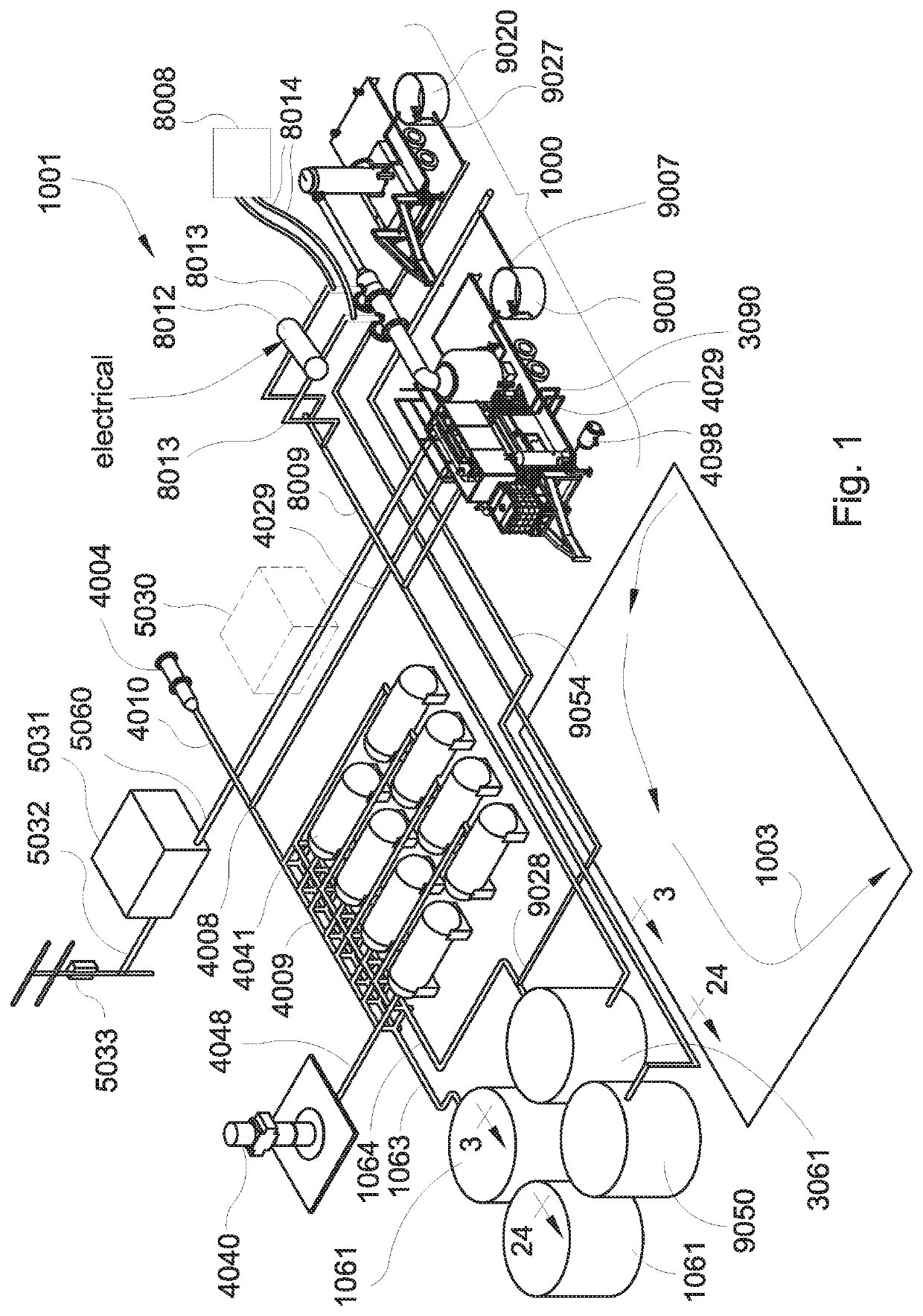
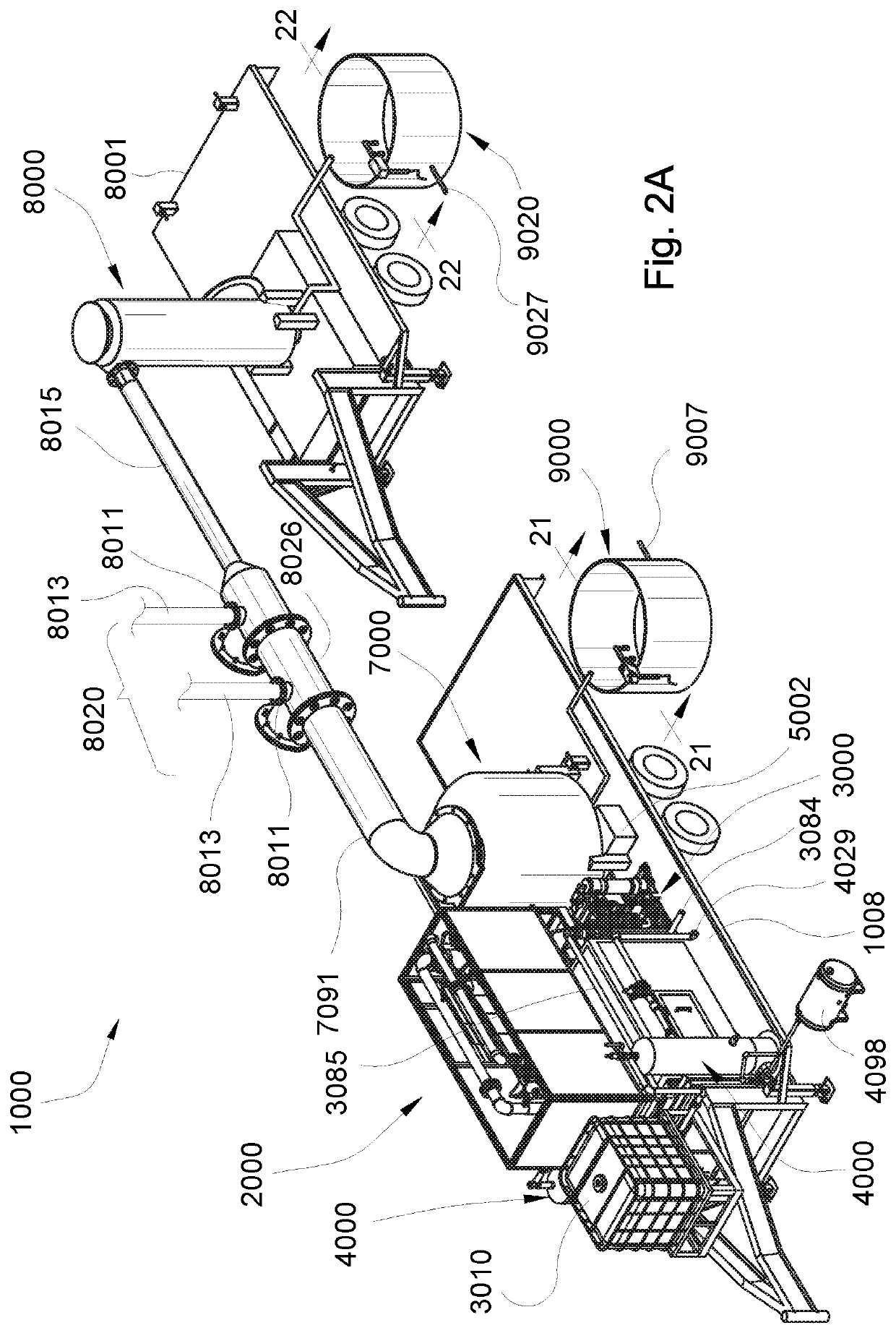
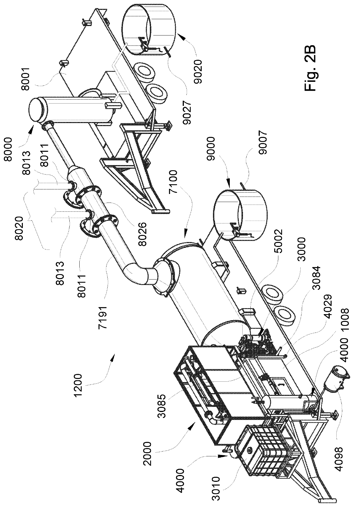
  • Evaporation apparatus for treating waste water
  • Evaporation apparatus for treating waste water
  • Evaporation apparatus for treating waste water

Examples


examples

[0357]Order and Timing of Sequence

[0358]Starting up the system and maintaining a burn proved problematic or impossible for reasons then unknown. Through many months of experimentation, it was discovered that several factors played a part, and the solution to the problem relied on addressing three overlapping factors in the timing and sequence of start-up events.

[0359]Multiple gas pressure drops resulted in an inconsistent delivery flow rate of gas that resulted in inability to start the system or automatic shut-down of the system shortly after start. If the fluid pressure was too high, the fluid would spray rather than cascade in the burner. If the fluid pressure was too low, however, there was not enough flow rate of fluid to prevent the burner from overheating. Depending on the type of fluid pump employed, it was discovered that water pressure of about 20 psig to about 50 psig (138-345 kPa), and more preferably, fluid pressure of about 30 psig to about 40 psig (207-276 kPa) is pre...


PUM

PropertyMeasurementUnit
angleaaaaaaaaaa
temperaturesaaaaaaaaaa
pressureaaaaaaaaaa

Abstract

A thin film, direct convection, evaporative apparatus, such as for treating waste water on-site at a production area or waste water processing area, relies on direct exposure of fluid to an open flame in a substantially enclosed burner unit having a burn chamber fed by an air-fuel mixing chamber and a fluid chamber, which apparatus also has gas and air trains and a metered fluid train permitting controlled fluid flow rate.

Description

BACKGROUND[0001]The field of the invention relates to methods and apparatuses for treating waste water. Examples of waste water that may be treated with the methods and apparatuses described include landfill leachate, chemical facility waste water, and high organic strength waste water. In particular, the methods and apparatuses are particularly suitable for use in the oil and gas industry where large amounts of waste water are produced.[0002]“Produced water” is waste water that is delivered to the surface of the ground during oil and gas production, and it includes water that was trapped previously in the natural ground formation, as well as flowback fluids that are injected during the process. In particular, hydraulic fracturing processes require a significant amount of injected water, a large portion of which flows back as produced water. It is estimated that U.S. oil production results in seven to ten barrels of produced water for each barrel of oil produced.[0003]Produced water...

Claims


Application Information

Patent Timeline
Patent Type & Authority Patents(United States)
IPC IPC(8): C02F1/04C02F1/68C02F1/00B04C3/06
CPCC02F1/048B04C3/06C02F1/004C02F1/68C02F2201/002C02F2103/06C02F2201/008C02F1/38B01D45/08B01D45/16B01D1/305C02F1/10B01D1/14C02F1/08
Inventor LOLLING, SHAWN MWARNER, JONATHAN C
Owner ABTECH IND
Learn More