
Underwater measurement of bioelectric signals

a bioelectric signal and underwater technology, applied in underwater equipment, medical science, diagnostics, etc., can solve the problems of degradation of resistive coupling quality over time, and difficult to establish good electrical contact, etc., to achieve convenient and effective measurement, small setup or intervention, and unobtrusive

Active Publication Date: 2021-09-21
QUANTUM APPLIED SCI & RES
View PDF29 Cites 2 Cited by
  • Summary
  • Abstract
  • Description
  • Claims
  • Application Information

AI Technical Summary

Benefits of technology

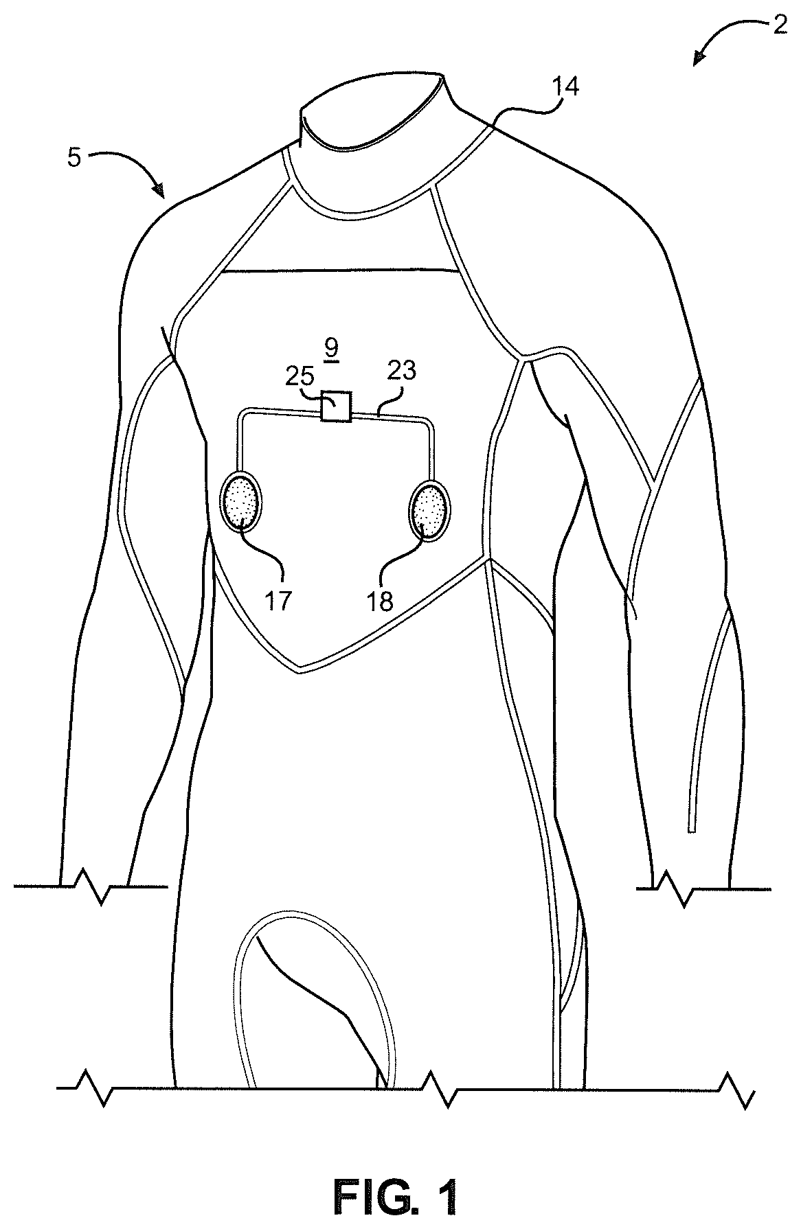
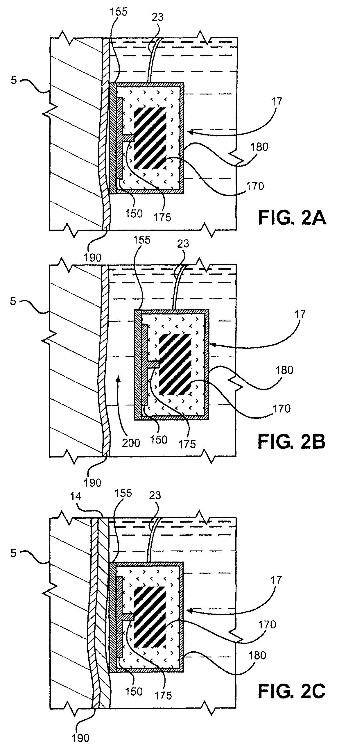
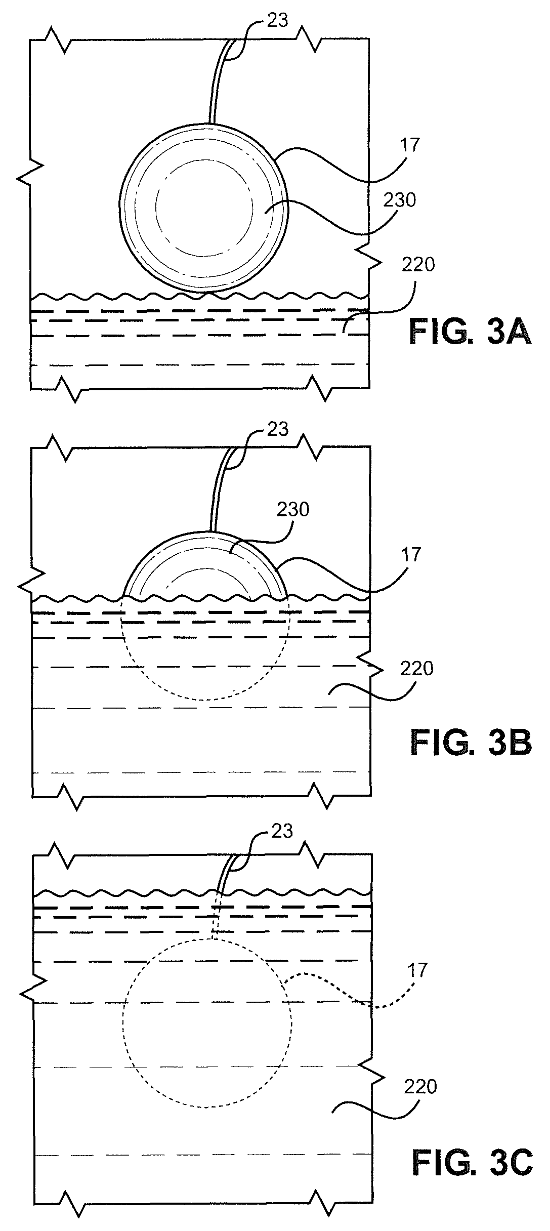
The patent describes a special sensor that can measure bioelectric signals underwater without being obtrusive or uncomfortable for the individual wearing the sensor. The sensor is protected from water and other substances that might affect it, and it can be easily integrated into a holding device. The method of measuring these signals is simple and can provide continuous monitoring without needing much attention or setup.

Problems solved by technology

The disadvantages of such resistive electrodes include discomfort for the subject, the requirement for conducting gels and / or adhesives, difficulty in establishing good electrical contact because of differing physical attributes of the subject (hair, skin properties, etc.), and the degradation in resistive coupling quality over time, among others.
These limitations have created a significant barrier to the use of resistive electrodes over extended periods of time and / or when convenience of use is paramount.
Resistive electrodes are especially ineffective when submersed in water.
The electrodes associated with these types of sensors are strongly affected by lift-off from the skin, particularly since the capacitive sensors are not used with conducting gels.
As a result, early capacitive sensors were not found to provide any meaningful benefits and were not generally adopted over resistive sensors.

Method used


Image

  • Underwater measurement of bioelectric signals
  • Underwater measurement of bioelectric signals
  • Underwater measurement of bioelectric signals

Examples


Embodiment Construction

[0033]Detailed embodiments of the present invention are disclosed herein. However, it is to be understood that the disclosed embodiments are merely exemplary of the invention that may be embodied in various and alternative forms. The figures are not necessarily to scale, and some features may be exaggerated or minimized to show details of particular components. Therefore, specific structural and functional details disclosed herein are not to be interpreted as limiting, but merely as a representative basis for teaching one skilled in the art to variously employ the present invention.

[0034]In the description which follows, like parts may be marked throughout the specification and drawing with the same reference numerals. The foregoing description of the figures is provided for a more complete understanding of the drawings. It should be understood, however, that the embodiments are not limited to the precise arrangements and configurations shown. Although the design and use of various ...


PUM


Abstract

A system and method of measuring bioelectric signals generated by an individual, inclusive of humans or other living organisms, comprises a plurality of sensors, at least one of the plurality of sensors being constituted by a capacitive-type sensor. Sensor has an associated insulated layer of material preventing the conduction of direct current between an electrode and individual, wherein a bioelectric signal of individual can be measured underwater.

Description

CROSS-REFERENCE TO RELATED APPLICATIONS[0001]The present application represents the U.S. National Phase of International Application number PCT / US2016 / 034671, which was filed on May 27, 2016, which claims the benefit of U.S. Provisional Application Ser. No. 62 / 167,059, which was filed on May 27, 2015 and titled “Underwater Measurement of Bioelectric Signals”. The entire content of this application is incorporated herein by reference.BACKGROUND OF THE INVENTION[0002]The present invention relates to the art of measuring bioelectric signals using sensor systems incorporating at least one capacitive-type electric sensor, with that sensor being at least partially underwater.[0003]It is widely known that electric potentials and fields are developed in free space from many different sources. For example, organs in the human body, including the heart and brain, produce electric fields throughout the body and in the space outside the body. For a variety of reasons, it is often desirable to m...

Claims


Application Information

Patent Timeline
Patent Type & Authority Patents(United States)
IPC IPC(8): A61B5/25A61B5/00A61B5/282A61B5/291A61B5/296A61B5/398A61B5/277A61B5/0205B63C11/12G01D5/24A61B5/28B63C11/06B63C11/24B63C11/04
CPCA61B5/6804A61B5/0205A61B5/25A61B5/277A61B5/282A61B5/291A61B5/296A61B5/398B63C11/12G01D5/24A61B5/28A61B2503/10A61B2562/0214A61B2562/182B63C11/06B63C11/24B63C2011/043B63C2011/046
Inventor FRIDMAN, IGOR V.MATTHEWS, ROBERT
Owner QUANTUM APPLIED SCI & RES
Learn More