Metallic foreign object detector, wireless power transmitting device, wireless power receiving device, and wireless power transmission system
a technology of metal foreign objects and detectors, applied in measurement devices, instruments, scientific instruments, etc., can solve the problems of deteriorating power feeding efficiency and inability to achieve power feeding, and achieve the effect of improving the accuracy of detection of metallic foreign objects
- Summary
- Abstract
- Description
- Claims
- Application Information
AI Technical Summary
Benefits of technology
Problems solved by technology
Method used
Image

Examples
first embodiment
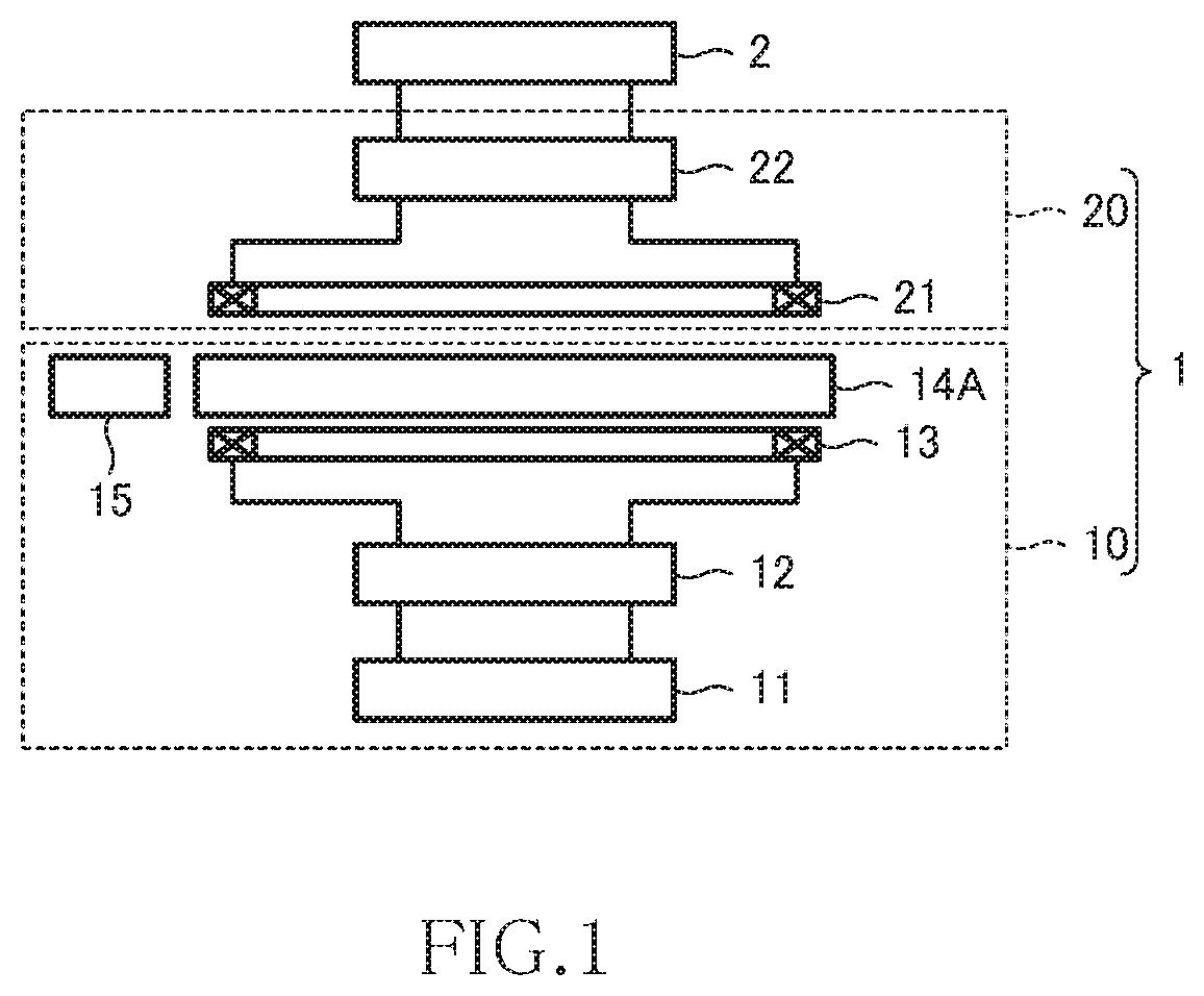
[0034]FIG. 1 is a view illustrating the schematic configuration of a wireless power transmission system 1 according to the first embodiment of the present invention and a load 2 connected to the wireless power transmission system 1. As illustrated, the wireless power transmission system 1 includes a wireless power transmitting device 10 and a wireless power receiving device 20. The load 2 is connected to the wireless power receiving device 20.
[0035]The wireless power transmission system 1 is a system used for power feeding to a moving body such as an electric vehicle (EV) or a hybrid vehicle (HV) that utilizes power from a secondary battery. In this case, the wireless power transmitting device 10 is mounted in power feeding facility installed on the ground, and the wireless power receiving device 20 is mounted on the vehicle. The following description will be given assuming that the wireless power transmission system 1 is a system for power feeding to the electric vehicle.
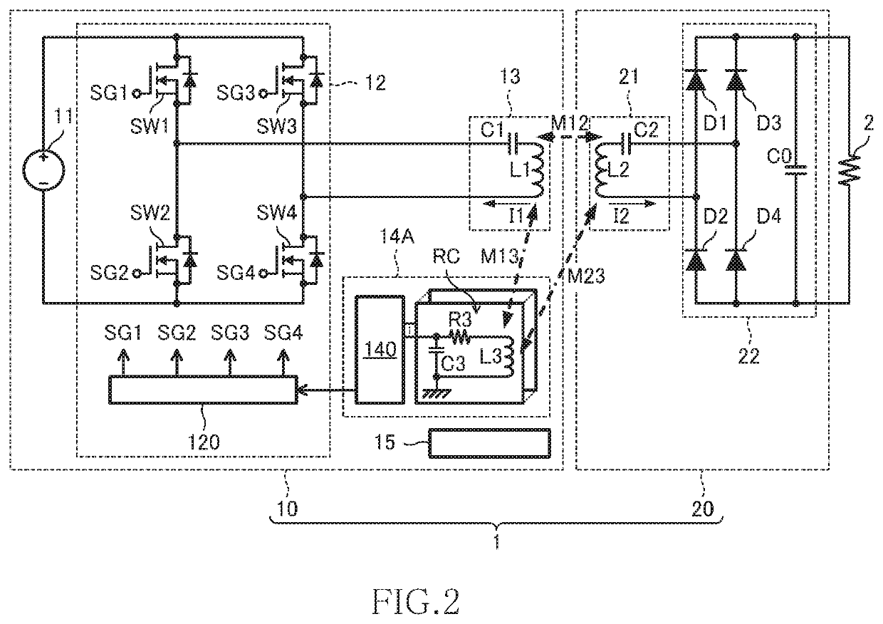
[0036]FIG....
second embodiment
[0083]The following describes the wireless power transmission system 1 according to a second embodiment of the present invention. The wireless power transmission system 1 according to the present embodiment differs from the wireless power transmission system 1 according to the first embodiment in that it uses a metallic foreign object detector 14B in place of the metallic foreign object detector 14A. Other configurations are the same as those of the wireless power transmission system 1 according to the first embodiment, so the same reference numerals are given to the same components as in the first embodiment, and description will be made focusing only on the difference from the first embodiment.
[0084]FIG. 8 is a schematic block diagram illustrating the functional block of the metallic foreign object detector 14B according to the present embodiment. As illustrated, the metallic foreign object detector 14B of the present embodiment additionally has a drive circuit 148 in the detectio...
third embodiment
[0096]The following describes the configuration of the wireless power transmission system according to a third embodiment of the present invention. The wireless power transmission system 1 according to the present embodiment differs from the wireless power transmission system 1 according to the first embodiment in that it uses a metallic foreign object detector 14C in place of the metallic foreign object detector 14A. Other configurations are the same as those of the wireless power transmission system 1 according to the first embodiment, so the same reference numerals are given to the same components as in the first embodiment, and description will be made focusing only on the difference from the first embodiment.
[0097]FIG. 10 is a schematic block diagram illustrating the functional block of the metallic foreign object detector 14C according to the present embodiment. As illustrated, the metallic foreign object detector 14C of the third embodiment includes a control circuit 147C in ...
PUM
 Abstract
Description
Claims
Application Information
 - R&D
- Intellectual Property
- Life Sciences
- Materials
- Tech Scout
- Unparalleled Data Quality
- Higher Quality Content
- 60% Fewer Hallucinations
Browse by: Latest US Patents, China's latest patents, Technical Efficacy Thesaurus, Application Domain, Technology Topic, Popular Technical Reports.
© 2025 PatSnap. All rights reserved.Legal|Privacy policy|Modern Slavery Act Transparency Statement|Sitemap|About US| Contact US: help@patsnap.com