Charging station comprising multiple batteries for charging electrical vehicles

a charging station and electrical vehicle technology, applied in the direction of several simultaneous battery arrangements, parallel/serial switching, safety/protection circuits, etc., can solve the problems of high power electronics, high cost, and high complexity of prior art charging stations, so as to reduce the risk of charging station malfunctioning considerably, simple and cost-effective circuitry, cost-effective manufacturing

Active Publication Date: 2021-08-10
NERVE SMART SYST APS
View PDF21 Cites 4 Cited by
  • Summary
  • Abstract
  • Description
  • Claims
  • Application Information

AI Technical Summary

Benefits of technology

[0024]By providing an electrical circuit element arranged to lead from the battery inlet line to the battery outlet line such as to form an electrical path leading around the battery cell, and one switch arranged in one of the battery outlet line and the battery inlet line, a charging station with very simple and cost efficient circuitry is provided for. In particular, the need for high power electronics as in all types of traditional charging stations is limited considerably, and the need for complex switching circuitry as in the solution of WO 2014 / 145756 is avoided altogether. Thus, the risk of the charging station malfunctioning is lowered considerably. Also, such a charging station is very cost efficient in manufacture and thus also to acquire.
[0046]Thereby a charging station with a particularly simple circuitry for not only switching battery packs between being charged and discharged but, if a neutral position is also provided for, even for coupling out an entire battery pack by is provided for, which in turn helps keeping down the manufacturing costs.

Problems solved by technology

Thus, the result is that charging stations for charging electrical vehicles, irrespective of whether the vehicles are of current or upcoming types, generally require the use of high power electronics, which is expensive.
Hence, the prior art charging stations comprise a significant amount of expensive high power electronics.
Both above-mentioned prior art solutions are, however, highly complex and require a large number of components, including a large amount of high power electronics, if they are to be rendered usable for charging electrical vehicles, and thus do not meet the above objects.
Also, charging stations for electrical vehicles are often to be placed at remote locations, which makes maintenance expensive as a technician must travel long distances to get to the charging station.
Therefore, such highly complex solutions, which may be more prone to malfunctioning, are not desirable in charging stations for electrical vehicles.

Method used


Image

  • Charging station comprising multiple batteries for charging electrical vehicles
  • Charging station comprising multiple batteries for charging electrical vehicles
  • Charging station comprising multiple batteries for charging electrical vehicles

Examples


first embodiment

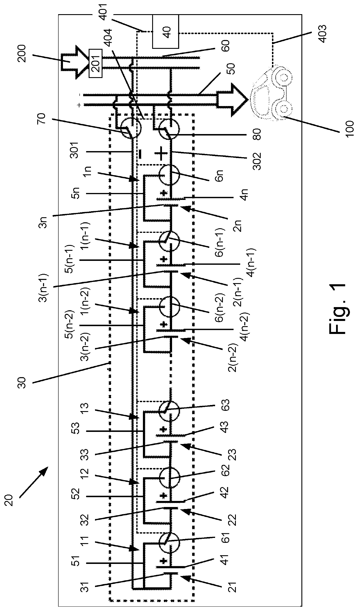
[0058]FIG. 1 illustrates a charging station 20 for charging electrical vehicles 100 according to the invention. The charging station 20 generally comprises a battery pack 30 with a plurality of n batteries 11, 12, 13, . . . 1(n−2), 1(n−1), 1n. The number n of batteries in a battery pack may be any number greater than or equal to 2. The batteries 11, 12, 13, . . . 1(n−2), 1(n−1), 1n are connected in series. The batteries 11, 12, 13, . . . 1(n−2), 1(n−1), 1n are all constructed in the same manner and will be described further below.

[0059]The battery pack 30 further comprises a first terminal 301 connected on one side to the negative terminal 31 of the battery cell 21 of the first battery 11 in the battery pack. The first terminal 301 thus forms a negative terminal of the battery pack. The first terminal 301 may on the other side be connected directly or indirectly to either an external source of electrical energy 200 or to an electrical vehicle 100 to be charged. A switch 70 is provid...

second embodiment

[0081]Turning finally to FIGS. 10 and 11, a battery 1′ of a battery pack 30 of a charging station 20 according to the invention is shown in the passive state and the active state, respectively. The battery 1′ differs from the battery 1 as shown in FIGS. 6 and 7 only in comprising a further switch 7 arranged in the battery inlet line 8, and thus between the negative terminal 3 of the battery cell 2 and the electrical circuit element 5.

[0082]The battery 1′ in other words comprise two switches 6 and 7, where the switch 6 is arranged in the battery outlet line 9, and thus between the positive terminal 4 of the battery cell 2 and the electrical circuit element 5, and where the switch 7 is arranged in the battery inlet line 8, and thus between the negative terminal 3 of the battery cell 2 and the electrical circuit element 5.

[0083]In charging stations 20 with battery packs 30 comprising batteries 1′ of the type shown in FIGS. 10 and 11, the control unit 40 is provided a connection line 40...


PUM

PropertyMeasurementUnit
electrical energyaaaaaaaaaa
electricalaaaaaaaaaa
poweraaaaaaaaaa

Abstract

A charging station for charging electrical vehicles and comprising battery pack(s). The battery pack(s) comprise(s) batteries coupled in series and a control unit for controlling the batteries individually. Each battery (1) comprises battery cell(s) with a battery inlet line and a battery outlet line, an electrical circuit element arranged to lead from the battery inlet line to the battery outlet line to form an electrical path leading around the battery cell, and one switch. The switch is arranged in the battery outlet line or the battery inlet line and is switchable between first and second positions. The control unit is connected to the switch of each battery and is adapted for controlling the switch to switch between the first position, in which an electrical power is lead through the battery cell, and the second position, in which the electrical power is lead through the electrical circuit element.

Description

RELATED APPLICATION DATA[0001]The present application is the U.S. National Phase of International Patent Application No. PCT / DK2017 / 050334, filed on Oct. 9, 2017 and entitled “CHARGING STATION FOR CHARGING ELECTRICAL VEHICLES,” which claims priority to Denmark Patent Application No. PA 201670819, filed on Oct. 18, 2016 and entitled “CHARGING STATION FOR CHARGING ELECTRICAL VEHICLES,” the contents of which are incorporated herein by reference in their entireties.FIELD OF THE INVENTION[0002]The present invention relates to charging stations for charging electrical vehicles. More particularly, the present invention relates to a charging station adapted for charging electrical vehicles and comprising at least one battery pack comprising a first terminal, a second terminal, and a plurality of batteries, the plurality of batteries being coupled in series between the first terminal and the second terminal, electrical coupling means adapted for coupling the first and second terminal of the ...

Claims


Application Information

Patent Timeline
Patent Type & Authority Patents(United States)
IPC IPC(8): B60L53/00B60L53/62B60L50/64B60L53/53B60L53/66B60L58/12H02J7/00H01M10/42H01M10/44H01M10/46H02J7/02
CPCB60L53/62B60L50/64B60L53/53B60L53/66B60L58/12H01M10/425H01M10/4207H01M10/441H01M10/46H02J7/005H02J7/0013H02J7/0045H02J7/0048H02J7/02H01M2010/4271H01M2220/10H01M2220/20H02J2207/20H01M10/443H02J7/0019H02J7/0024G01R31/396B60L53/31H02J7/342Y02T10/70Y02T90/16Y02T10/7072Y02T90/12Y02E60/10H02J7/00302H02J7/00306H02J7/007194Y02T90/14B60L58/10B60L2210/30B60L2250/16B60Y2200/91Y02T10/72
Inventor RASMUSSEN, JESPER B.
Owner NERVE SMART SYST APS
Why Eureka
Try Eureka