Thermoelectric generator with starting circuit

a technology of starting circuit and generator, which is applied in the direction of electric variable regulation, process and machine control, instruments, etc., can solve the problems that the dc to dc voltage converter available on the market cannot work with a high efficiency with ultra-low voltage inputs, and achieve the effect of avoiding the use of pn junctions or high electron mobility field effect transistors, effective modulation of the conductivity of depletion transistors, and poor electrical performan

Active Publication Date: 2021-08-03
THE SWATCH GRP RES & DEVELONMENT LTD
View PDF9 Cites 0 Cited by
  • Summary
  • Abstract
  • Description
  • Claims
  • Application Information

AI Technical Summary

Benefits of technology

[0010]Such low operating input voltage levels allow the use of a simple thermoelectric element, with a limited number of PN type elements, presenting a significant manufacturing cost reduction. Such step-up DC to DC converters with ultra-low starting voltage levels allow thus to build self-powered applications with temperature differences as small as 1° C. to 5° C. and thermoelectric elements with no more than 5 pairs of PN elements.
[0034]According to another embodiment the fourth switch is a highly conductive depletion type MOS transistor having a channel resistance value below 100 milliOhm at a gate to source voltage of 0 V. Typically, the fourth switch and hence the second metal oxide semiconductor transistor is placed between the source of the first transistor, hence the source of the depletion transistor and ground. In this way operation of the starting circuit can be stopped once its function is performed. The rather low channel resistance of the second metal oxide semiconductor transistor is beneficial in order to only introduce a minimal voltage drop at the start of an oscillation of the self-oscillating starting circuit in order to maintain the conversion efficiency of the starting circuit.

Problems solved by technology

Nevertheless, DC to DC voltage converters available on the market are unable to work with a high efficiency with ultra-low voltage inputs, typically a few milliVolts.

Method used


Image

  • Thermoelectric generator with starting circuit
  • Thermoelectric generator with starting circuit

Examples


Embodiment Construction

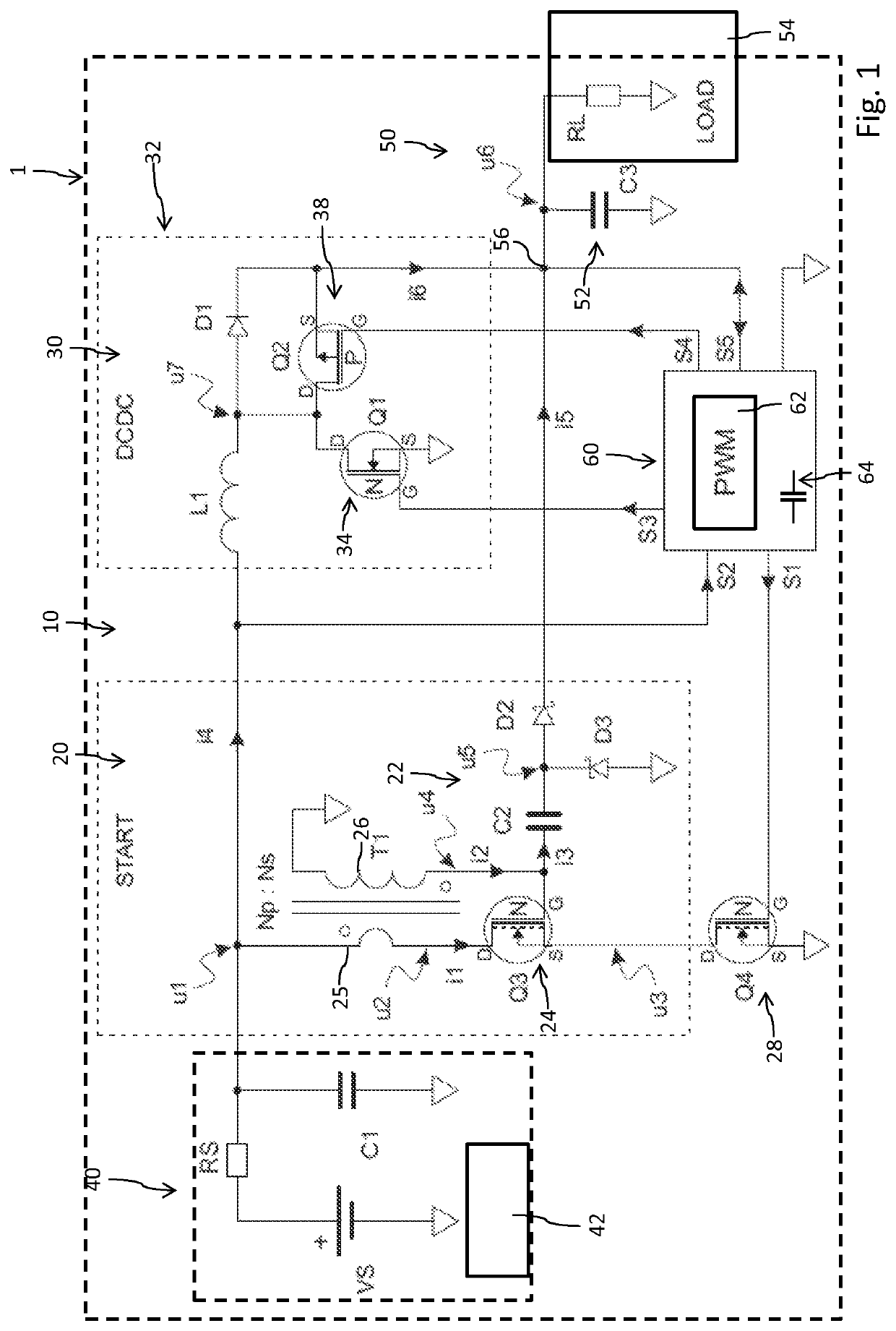
[0041]In FIG. 1 a schematic illustration of an embodiment of the thermoelectric generator 10 is provided. The thermoelectric generator 10 comprises a voltage source 40 and a starting circuit 20 that is connected to the voltage source 40. The thermoelectric generator 10 further comprises a DC to DC converter circuit 30 that is also connected to the voltage source 40. There is further provided an output 50 connected to a load 54 or connectable to a load 54. The output 50 is connected to the DC to DC converter 30 as well as to the starting circuit 20. In other words, there is provided an output node 56 that is connected to both, the starting circuit 20 as well as to the DC to DC converter circuit 30.

[0042]The thermoelectric generator 10 further comprises a controller 60 connected to the starting circuit 20 and connected to the DC to DC converter circuit 30. The controller 60 is connected to the starting circuit 20 via the connection S1. The controller 60 is further connected to the vol...


PUM

PropertyMeasurementUnit
temperatureaaaaaaaaaa
voltageaaaaaaaaaa
input voltageaaaaaaaaaa

Abstract

A thermoelectric generator includes a voltage source including a thermoelectric element, a starting circuit connected to the voltage source, a DC to DC converter circuit connected to the voltage source, an output connected to the starting circuit and connected to the DC to DC converter circuit, and a controller having an input connected to the voltage source, and outputs connected to the starting circuit and to the DC to DC converter circuit. The controller deactivates the starting circuit and activates the DC to DC converter circuit when a voltage at the output or when a voltage provided by the voltage source rises above a predefined upper voltage threshold. Additionally, the controller reactivates the starting circuit and deactivates the DC to DC converter circuit when a voltage at the output or when a voltage provided by the voltage source drops below a predefined lower voltage threshold.

Description

[0001]This application claims priority from European Patent Application No. 17181591.3 filed on Jul. 17, 2017; the entire disclosure of which is incorporated herein by reference.DESCRIPTION[0002]The present invention relates to a thermoelectric generator as well as to a mobile electronic device comprising such a thermoelectric generator. Moreover the invention relates to a voltage converter providing conversion of an ultra-low input voltage into a usable output voltage over a large range of output power.BACKGROUND[0003]A thermoelectric generator (TEG), also called Seebeck generator, is a device that converts heat flux directly into electrical energy through a phenomenon called the Seebeck effect. A thermoelectric generator typically includes a thermoelectric element comprising of a number of pairs of a P type element and an N type element. These elements are placed in parallel between two plates, and electrically connected in series, alternating P and N type elements. The temperatur...

Claims


Application Information

Patent Timeline
Patent Type & Authority Patents(United States)
IPC IPC(8): H02M1/36H02M3/156H01L35/28H02M3/158H01M8/18H02M3/155
CPCH02M1/36H01L35/28H01M8/182H02M3/158H02M3/1582H02M3/156H02M2003/1552H02M1/088Y02E60/50H02M3/1552H10N10/10
Inventor GUEISSAZ, FRANCOIS
Owner THE SWATCH GRP RES & DEVELONMENT LTD
Why Eureka
Try Eureka