
Hydrogen refueling system

a technology of refueling system and hydrogen, which is applied in the direction of fixed capacity gas holders, gas/liquid distribution and storage, vessel construction details, etc., can solve the problems of high electricity costs, insufficient speed of nominal filling of fcv tanks, and observation of permanent power consumption, so as to achieve fast cooling of heat exchangers and temperature regulation

Active Publication Date: 2021-08-03
LAIR LIQUIDE SA POUR LETUDE & LEXPLOITATION DES PROCEDES GEORGES CLAUDE
View PDF4 Cites 1 Cited by
  • Summary
  • Abstract
  • Description
  • Claims
  • Application Information

AI Technical Summary

Benefits of technology

The present invention provides a hydrogen refueling system that can cool down the heat exchanger quickly when a vehicle enters the refueling station, allowing for quicker refueling. The system includes a cold generation valve located close to the heat exchanger inlet, which cools down the refrigerant circulating between the chiller and the dispenser. This reduces the time needed to cool the heat exchanger and allows for faster refueling of the vehicle. Additionally, a high pressure receiver may be used to accumulate refrigerant to provide high cooling power during a limited period of time, further improving the system's efficiency.

Problems solved by technology

Without pre-cooling, the nominal filling of FCV tank could not be achieved fast enough.
Also, due to frigorific losses of the system, even though no cold is needed for H2 refueling, permanent power consumption is observed during opening times of HRS.
It causes high electricity costs even if during long periods of time, no FCV refueling is performed.
This is not efficient and savings could be achieved if it was possible to stop the chiller during idle time of the HRS.
In the current situation, this is not possible because the time needed to cool down all the elements within the dotted line of FIG. 3 could not be accepted as waiting time for the customer.

Method used


Image

  • Hydrogen refueling system
  • Hydrogen refueling system
  • Hydrogen refueling system

Examples


embodiment 1

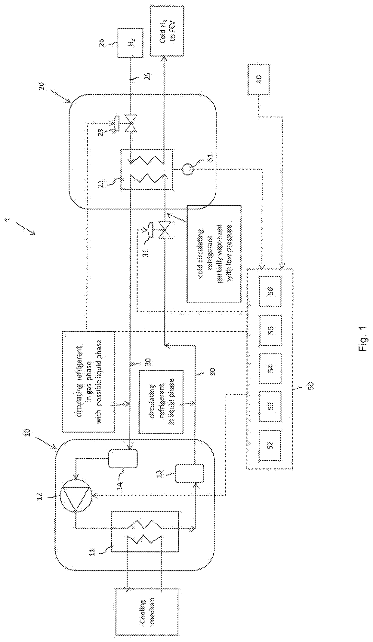
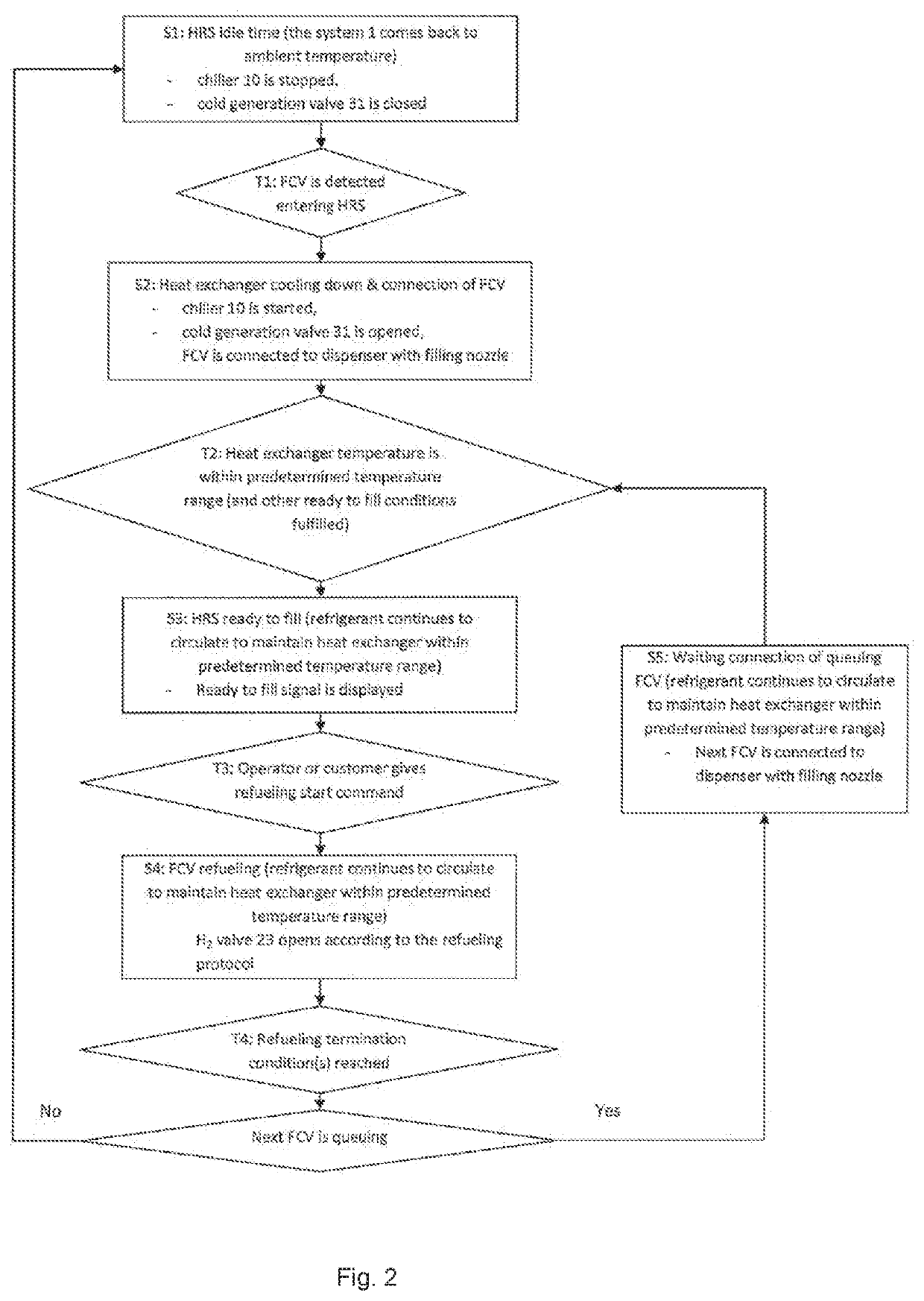
[0096]The hydrogen refueling system 1 of the first embodiment is explained by referring FIGS. 1 and 2. The hydrogen refueling system 1 includes Chiller 10, Dispenser 20 and Circulation line 30.

[0097]First, Chiller 10 is explained below. The low pressure receiver (LPR) 14 is provided within Chiller 10. LPR 14 is fed by the circulating refrigerant returned from the heat exchanger 21 of Dispenser 20. LPR 14 can separate into gas phase and liquid phase from of the circulating refrigerant. In case that the circulating refrigerant is a fluid mixture which has gas phase and liquid phase of the circulating refrigerant, LPR 14 can separate into gas phase of the circulating refrigerant and liquid phase of the circulating refrigerant. The liquid phase of refrigerant can be stored at bottom of LPR 14. When the vehicle detection system 40 detects the vehicle, the chiller compressor 12 is started and the circulating refrigerant in the gas phase can be fed to the cooling unit 11 after passing thro...

example 1

[0159]Currently, the weight of compact stainless steel diffusion bonded heat exchangers used in H2 dispensers can be around 150 kg. Around 5000 kJ are necessary to cool down the mass of the heat exchanger from 30° C. to −40° C.

[0160]This could be achieved within 3 minutes with around 30 kW frigorific power. Such power is achievable with small size compact chillers. Shorter cooling time or reduced chiller frigorific power could be achieved by using the strategy of storing some amount of liquid refrigerant in HPR as described above.

[0161]While the invention has been described in conjunction with specific embodiments thereof, it is evident that many alternatives, modifications, and variations will be apparent to those skilled in the art in light of the foregoing description. Accordingly, it is intended to embrace all such alternatives, modifications, and variations as fall within the spirit and broad scope of the appended claims. The present invention may suitably comprise, consist or ...


PUM


Abstract

The present invention is to provide a hydrogen refueling system capable to cool down the H2 pre-cooling heat exchanger fast enough when a FCV enters the HRS, so that there is no or very minimal waiting time for the customer before starting refueling. A hydrogen refueling system includes a chiller including a cooling unit that cools a circulating refrigerant by a cooling medium, a dispenser that supplies H2 to a vehicle, including a heat exchanger that cools H2 with the circulating refrigerant provided from the chiller, a circulation line that circulates the circulating refrigerant between the cooling unit and the heat exchanger, a chiller compressor that is provided in the chiller; a cold generation valve that is provided close to an inlet of the heat exchanger in the circulation line.

Description

CROSS-REFERENCE TO RELATED APPLICATIONS[0001]This application is a § 371 of International PCT Application PCT / JP2016 / 005073, filed Dec. 6, 2016.BACKGROUND ARTField of the Invention[0002]The present invention relates to a hydrogen refueling system, for example a hydrogen refueling station (HRS).Description of the Related Art[0003]According to current standards of refueling protocols, to achieve fast refueling of Fuel Cell Vehicles (FCV) tanks with 70 MPa nominal hydrogen refueling pressure, the hydrogen needs to be pre-cooled below −33° C., at dispenser outlet, in order to avoid overheating in FCV tank by adiabatic compression.[0004]Today, this is done by having one heat exchanger, typically compact diffusion bonded heat exchanger, installed in the dispenser 520, and fed with a heat carrying fluid, typically brine (see FIG. 3, prior art). The heat carrying fluid is circulated between the traditional chiller 510 using refrigerant and the dispenser 520 by means of a pump.[0005]In order...

Claims


Application Information

Patent Timeline
Patent Type & Authority Patents(United States)
IPC IPC(8): F17C7/00
CPCF17C7/00F17C2205/0323F17C2221/012F17C2223/035F17C2227/0157F17C2227/0355F17C2250/032F17C2250/0631F17C2250/0678F17C2265/065F17C2270/0139F17C2223/036F17C2227/0341F17C2227/036Y02E60/32
Inventor WERLEN, ETIENNEOTT, THIERRY
Owner LAIR LIQUIDE SA POUR LETUDE & LEXPLOITATION DES PROCEDES GEORGES CLAUDE
Learn More