
Hydrogen refueling system

a technology of refueling system and hydrogen, which is applied in the direction of electrochemical generators, gas/liquid distribution and storage, vessel construction details, etc., can solve the problems of high electricity cost, insufficient speed of nominal filling of fcv tank, and observation of permanent power consumption, so as to achieve fast cooling of heat exchanger and temperature regulation

Active Publication Date: 2020-03-05
LAIR LIQUIDE SA POUR LETUDE & LEXPLOITATION DES PROCEDES GEORGES CLAUDE
View PDF3 Cites 1 Cited by
  • Summary
  • Abstract
  • Description
  • Claims
  • Application Information

AI Technical Summary

Benefits of technology

The present invention provides a hydrogen refueling system that can quickly cool down the hydrogen pre-cooling heat exchanger when a vehicle enters the refueling area, reducing waiting time for the customer before starting refueling. The system uses cold fluid from a cryogenic tank to cool the heat exchanger while the vehicle is still in the idle area. This allows for quick refueling without the need for excessive cooling of other equipment.

Problems solved by technology

Without pre-cooling, the nominal filling of FCV tank could not be achieved fast enough.
Also, due to frigorific losses of the system, even though no cold is needed for H2 refueling, permanent power consumption is observed during opening times of HRS.
It causes high electricity costs even if during long periods of time, no FCV refueling is performed.
This is not efficient and savings could be achieved if it was possible to stop the chiller during idle time of the HRS.
In the current situation, this is not possible because the time needed to cool down all the elements within the dotted line of FIG. 3 could not be accepted as waiting time for the customer.

Method used


Image

  • Hydrogen refueling system
  • Hydrogen refueling system
  • Hydrogen refueling system

Examples


embodiment 1

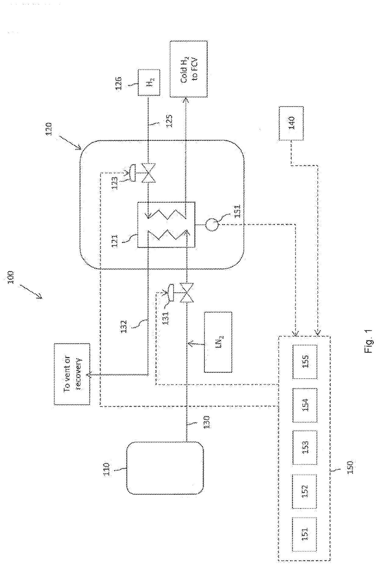
[0074]The hydrogen refueling system 100 of the first embodiment is explained by referring FIGS. 1 and 2. The hydrogen refueling system 100 includes a liquid nitrogen (LN2) tank 110 and Dispenser 120. LN2 tank 110 stores the liquid nitrogen (LN2).

[0075]First, Dispenser 120 is explained below.

[0076]Dispenser 120 supplies H2 to a vehicle. Dispenser 120 includes the heat exchanger 121 that cools H2 with LN2 provided from the LN2 tank 110. Dispenser 120 includes the dispenser hose and the refueling nozzle for refueling H2 to a vehicle.

[0077]In this embodiment, the temperature control unit 151 measures the temperature (t1) of the heat exchanger metal mass. The temperature control unit 151 may measures the temperature at a wall of the heat exchanger 121, at a channel of the outlet line 132 within the heat exchanger 121. In this embodiment, the temperature control unit 151 includes both function of a temperature measuring unit and a valve control unit.

[0078]In other embodiment, the temperat...

example 1

[0117]Currently, the weight of compact stainless steel diffusion bonded heat exchangers used in H2 dispensers can be around 150 kg. Around 5000 kJ are necessary to cool down the mass of the heat exchanger from 30° C. to −40° C.

[0118]This could be achieved within 3 minutes with around 30 kW frigorific power. Such power is achievable by injection of ˜500 l / h of liquid nitrogen.

[0119]While the invention has been described in conjunction with specific embodiments thereof, it is evident that many alternatives, modifications, and variations will be apparent to those skilled in the art in light of the foregoing description. Accordingly, it is intended to embrace all such alternatives, modifications, and variations as fall within the spirit and broad scope of the appended claims. The present invention may suitably comprise, consist or consist essentially of the elements disclosed and may be practiced in the absence of an element not disclosed. Furthermore, if there is language referring to ...


PUM


Abstract

The present invention is to provide a hydrogen refueling system capable to cool down the H2 pre-cooling heat exchanger fast enough when a FCV enters the HRS, so that there is no or very minimal waiting time for the customer before starting refueling. A hydrogen refueling system including a cryogenic fluid tank that stores a cryogenic fluid, a dispenser that supplies H2 to a vehicle, including a heat exchanger that cools H2 with the cold and / or cryogenic fluid provided from the cryogenic fluid tank, an inlet line that sends the cold and / or cryogenic fluid to the heat exchanger from the cryogenic fluid tank, an outlet line that collects the cryogenic fluid fed from the heat exchanger, and an injection valve that is provided in the inlet line.

Description

CROSS-REFERENCE TO RELATED APPLICATIONS[0001]This application is a § 371 of International PCT Application PCT / JP2016 / 005074, filed Dec. 6, 2016.BACKGROUND ARTField of the Invention[0002]The present invention relates to a hydrogen refueling system, for example a hydrogen refueling station (HRS).Related Art[0003]According to current standards of refueling protocols, to achieve fast refueling of Fuel Cell Vehicles (FCV) tanks with 70 MPa nominal hydrogen refueling pressure, the hydrogen needs to be pre-cooled below −33° C., at dispenser outlet, in order to avoid overheating in FCV tank by adiabatic compression.[0004]Today, this is done by having one heat exchanger, typically compact diffusion bonded heat exchanger, installed in the dispenser 520, and fed with a heat carrying fluid, typically brine (see FIG. 3, prior art). The heat carrying fluid is circulated between the traditional chiller 510 using refrigerant and the dispenser 520 by means of a pump.[0005]In order to keep the HRS re...

Claims


Application Information

Patent Timeline
IPC IPC(8): F17C5/00F17C13/02
CPCF17C13/025F17C2250/032F17C2270/0139F17C2221/012F17C2265/065F17C5/007F17C2250/043F17C2250/0439F17C2270/0184F17C2205/0326F17C2223/0123F17C2223/036F17C2227/0309F17C2227/0323F17C2250/03F17C2250/0478F17C2250/0694Y02E60/32
Inventor WERLEN, ETIENNEOTT, THIERRY
Owner LAIR LIQUIDE SA POUR LETUDE & LEXPLOITATION DES PROCEDES GEORGES CLAUDE
Learn More