Batch furnace for annealing material and method for heat treatment

a technology of annealing material and heat treatment, which is applied in the direction of heat treatment apparatus, furnaces, domestic stoves or ranges, etc., can solve the problems of large energy loss or correspondingly extensive thermal insulation measures, and achieve the effect of greater heat treatment efficiency

Active Publication Date: 2021-07-20
GAUTSCHI ENG GMBH
View PDF15 Cites 0 Cited by
  • Summary
  • Abstract
  • Description
  • Claims
  • Application Information

AI Technical Summary

Benefits of technology

[0013]The invention named here manages without nozzles or respectively a nozzle system, which is used in the prior art in order to act upon the furnace material with the heat transfer medium. Thereby, the flow channels provided in the prior art, which are arranged in the receiving chamber of the furnace housing and provide the nozzles with the heat transfer medium, are dispensed with. One therefore also speaks of an open volume of the furnace housing. The elimination of the flow channels and of the nozzles shortens the flow paths and reduces the pressure losses. With regard to a single coil furnace, the invention enables the reducing in size of the intake region of the fan above the furnace material or respectively the coil. The flushing losses with the use of a protective gas atmosphere are reduced owing to the efficiently used furnace volume. Through the compact construction, the space requirement of the furnace and the outer surface of the furnace which is to be insulated are reduced. Thereby, heat losses are reduced without additional heat insulation measures.
[0038]According to a further preferred embodiment, the separable housing part is constructed in one piece or divided with a cover or with pivotable wings. The one-piece variant is simple in construction. The divided variant enables a good access to the furnace material during charging or respectively removal.

Problems solved by technology

The known chamber furnaces and single coil furnaces are complex in construction and relatively large, which leads to correspondingly great energy losses or respectively correspondingly extensive thermal insulation measures.

Method used


Image

  • Batch furnace for annealing material and method for heat treatment
  • Batch furnace for annealing material and method for heat treatment
  • Batch furnace for annealing material and method for heat treatment

Examples


Embodiment Construction

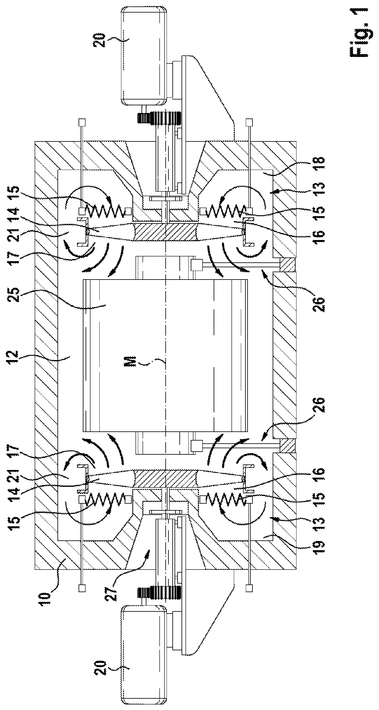
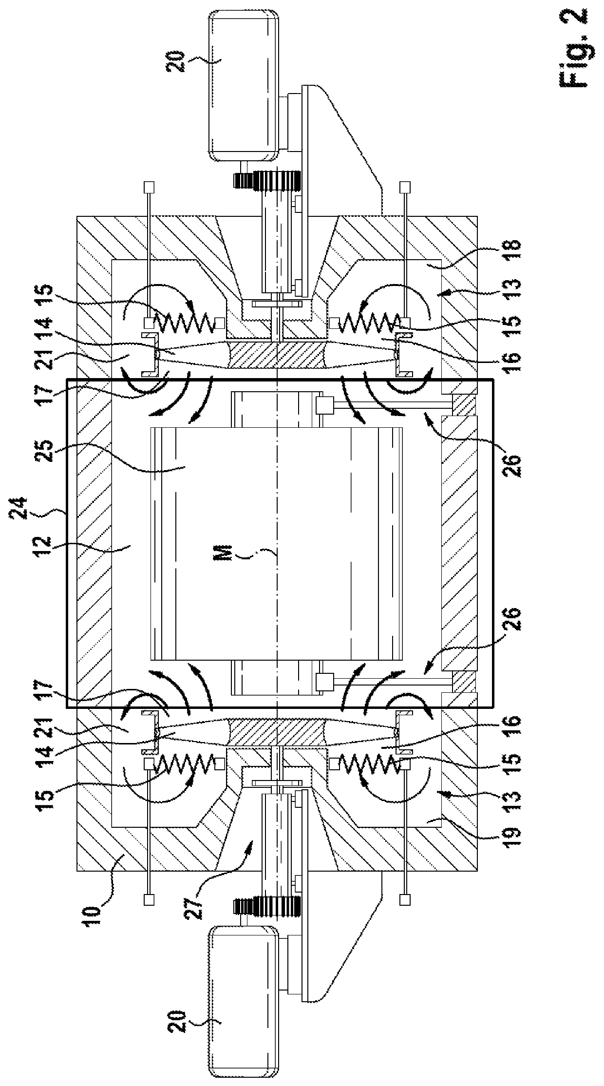
[0049]The batch furnace according to FIG. 1 is used preferably, but not exclusively, for the heat treatment of aluminum annealing material, for example of aluminum coils. The coil illustrated in FIG. 1 has reference number 25. The batch furnace is able to be used generally for coils (irrespective of material) or other annealing material.

[0050]The batch furnace is in practical terms a single coil furnace, which is adapted for the heat treatment of individual coils. The invention is also able to be applied to single chamber furnaces which are suitable for the heat treatment of billets, rolling ingots or coils.

[0051]The batch furnace has a furnace housing 10 with a thermal insulation. The furnace housing can have a cylindrical shape. Other furnace shapes are possible. The furnace housing 10 delimits a receiving chamber 12 in which the furnace material or respectively the annealing material is arranged during operation of the batch furnace. The concern here is with an individual receivi...


PUM

PropertyMeasurementUnit
pressureaaaaaaaaaa
electrical resistanceaaaaaaaaaa
convective heat transferaaaaaaaaaa

Abstract

A batch furnace for annealing material, in particular a single chamber furnace or single coil furnace, with a furnace housing. The batch furnace has a closable charging opening, a receiving chamber for receiving furnace material, and a device for convective heat transfer onto the furnace material by a heat transfer medium. The batch furnace includes at least one fan, which is arranged in the furnace housing, at least one heating device for the heat transfer medium and / or at least one inlet for an externally heated heat transfer medium, wherein the heating device and / or the inlet is arranged directly in front of the intake side or directly behind the pressure side of the fan or circumferentially in an annular gap between the fan and the furnace housing, and a receiving chamber for the furnace material, which is arranged on the pressure side of the fan.

Description

BACKGROUND OF THE INVENTION1. Field of the Invention[0001]The invention relates to a batch furnace for annealing material and a method for heat treatment.2. Discussion of the Related Art[0002]In industrial furnace construction, a differentiation is made between continuous furnaces and batch furnaces. Batch furnaces have an enclosed furnace chamber, in which an individual batch is heat-treated. Examples of batch furnaces are single coil furnaces, which enable a flexible and individual heat treatment of individual coils. A further example of a batch furnace are so-called chamber furnaces, which are used for the heat treatment of coils, billets and rolling ingots. Such a chamber furnace is known for example from DE 102 27 499 A1.[0003]Known batch furnaces have flow directing systems for example with nozzles, which direct and introduce the heat transfer medium in the furnace chamber and act upon the batch, situated in the furnace chamber, with the heat transfer medium for convective hea...

Claims


Application Information

Patent Timeline
Patent Type & Authority Patents(United States)
IPC IPC(8): C21D1/767C21D9/54C21D1/40C21D9/52C21D9/68F24C15/32F27B17/00F27D7/04
CPCC21D1/767C21D1/40C21D9/525C21D9/54C21D9/68F24C15/325F27B17/0016F27D2007/045
Inventor EHMANN, RAINER
Owner GAUTSCHI ENG GMBH
Why Eureka
Try Eureka