
Ophthalmic measurement device and ophthalmic measurement system

a measurement device and ophthalmology technology, applied in the field ophthalmology measurement systems, can solve the problems of ophthalmology measurement devices, ophthalmology measurement devices, and requires a structure, and achieve the effect of accurate measurement and accurate measuremen

Active Publication Date: 2021-07-13
ELRISE CORP
View PDF17 Cites 1 Cited by
  • Summary
  • Abstract
  • Description
  • Claims
  • Application Information

AI Technical Summary

Benefits of technology

[0007]The present invention is to solve the above-described problems. An object of the present invention is to provide an ophthalmic measurement device and an ophthalmic measurement system which can accurately measure a curvature radius of a tear fluid meniscus even when a distance between an eyelid of a measurement subject and a projection means changes during the measurement of the curvature radius of a tear fluid meniscus.
[0010]According to the present invention, the curvature radius of a tear fluid meniscus can be accurately measured even when the distance between the ophthalmic measurement device and a lower eyelid changes. Therefore, the tear fluid volume of a measurement subject can be accurately measured. Furthermore, the need for positioning between the ophthalmic measurement device and an eyelid is eliminated. Therefore, the tear fluid volume can be measured with general-purpose apparatuses such as smartphones, notebook computers, and head mount displays. Moreover, the tear fluid volume can be measured while a measurement subject operates a smartphone. Thus, information for preventing dry eye such as Visual Display Terminal (VDT) syndrome caused by overuse of an eye during VDT operations can also be collected.

Problems solved by technology

Therefore, the ophthalmic measurement device had a problem that it requires a structure for fixing the position of a head, such as placing a chin on a chin table and bringing a forehead into contact with a disposed bar.
Therefore, the ophthalmic measurement device had another problem that a measurement error occurs.

Method used


Image

  • Ophthalmic measurement device and ophthalmic measurement system
  • Ophthalmic measurement device and ophthalmic measurement system
  • Ophthalmic measurement device and ophthalmic measurement system

Examples


embodiment 1

Effects of Embodiment 1

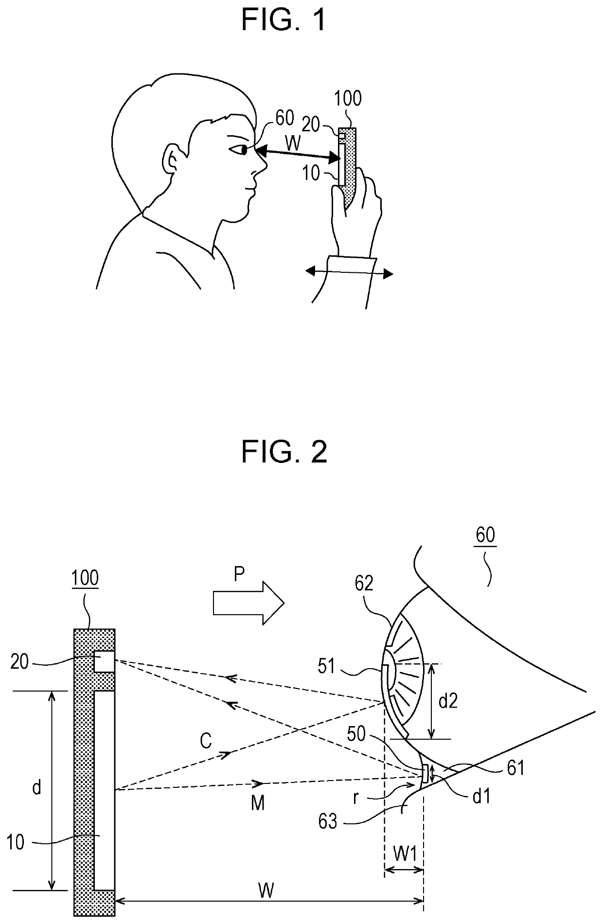
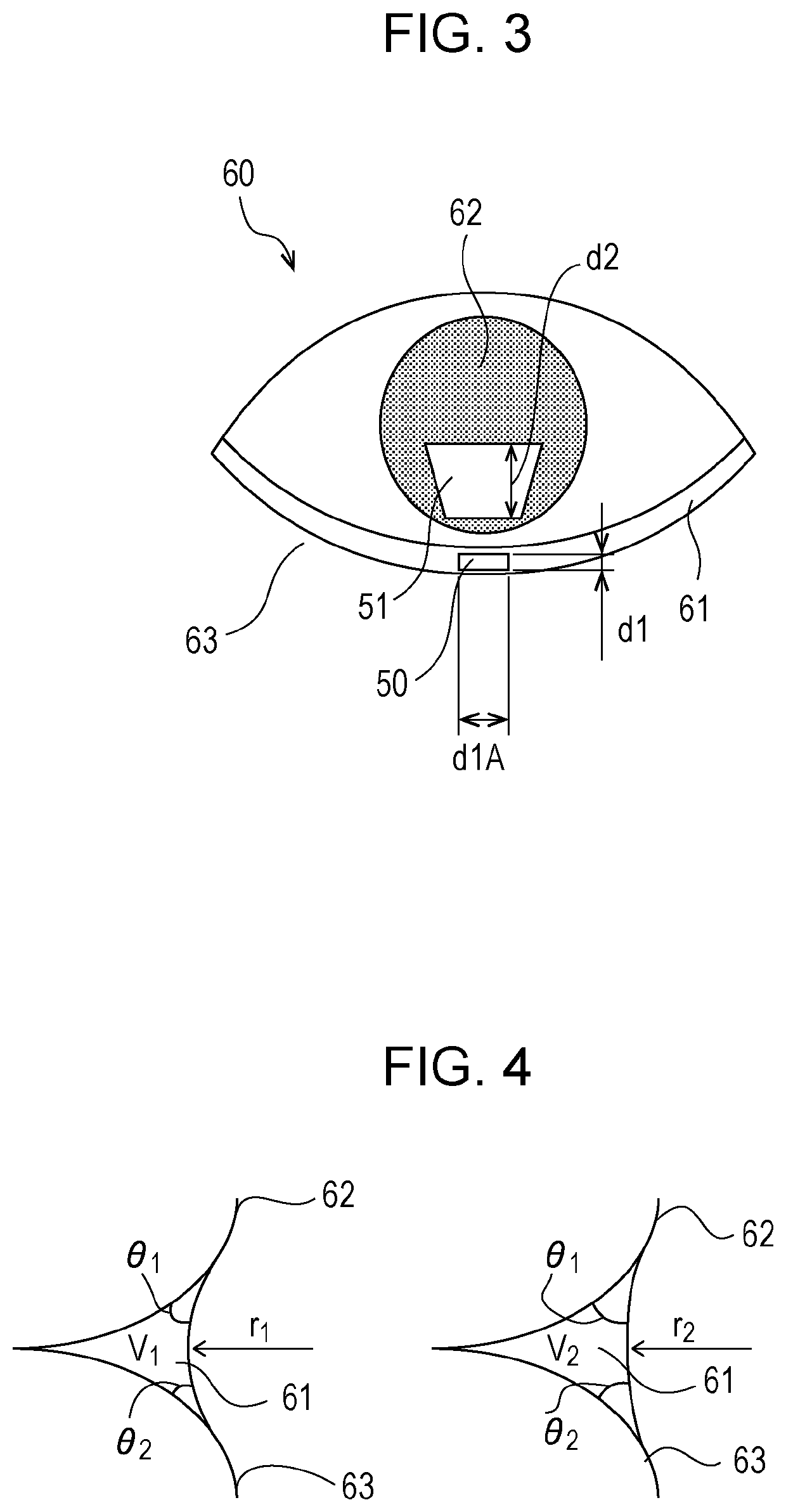
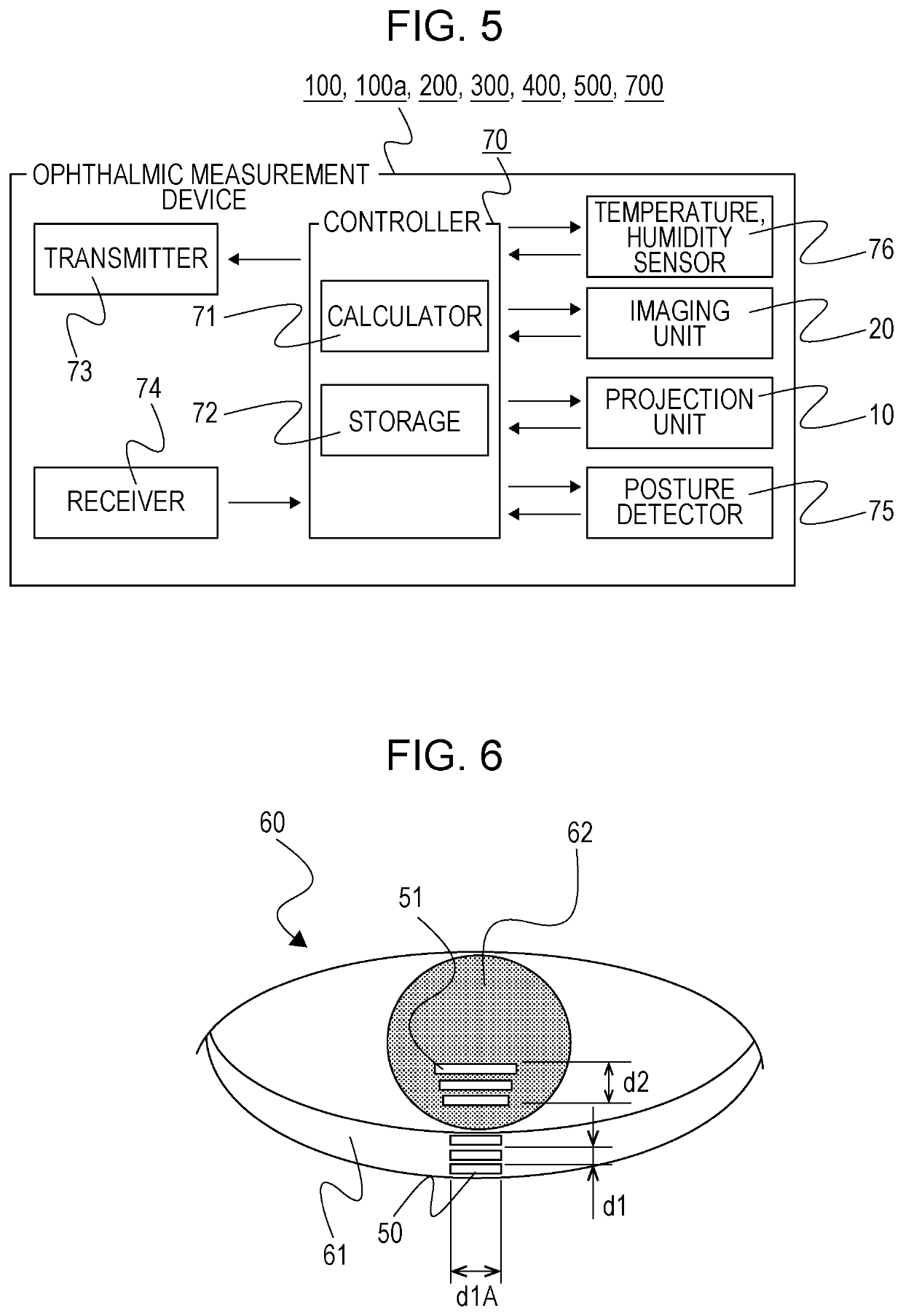
[0053]According to the ophthalmic measurement devices 100 and 100a of Embodiment 1, the curvature radius r of the surface of the lower eyelid tear fluid 61 can be measured without fixing the distance between the ophthalmic measurement device 100 or 100a and the eye 60, particularly the distance W between the ophthalmic measurement device 100 or 100a and the surface of the lower eyelid tear fluid 61. Also, the ophthalmic measurement devices 100 and 100a have an advantage in that the curvature radius r of the surface of the lower eyelid tear fluid 61 can be measured while a measurement subject oneself holds the ophthalmic measurement devices 100 and 100a with the hand. Furthermore, since a portable communication terminal such as a smartphone, and the like can be used as the ophthalmic measurement devices 100 and 100a, the physical quantity of tear fluid of the eye 60 can be measured during the usual use of a smartphone. Thus, a self-check of dry eye is facilitat...

embodiment 2

Effects of Embodiment 2

[0057]According to the ophthalmic measurement device 200 of Embodiment 2, infrared light is projected from the projection unit 10 to the lower eyelid tear fluid 61 and the cornea and conjunctiva 62, thereby enabling the measurement of the curvature radius r of the lower eyelid tear fluid 61 without exposing a measurement subject to the glare caused by projection. Therefore, tear fluid is unlikely to be secreted due to the reflexes of the human body, and the measurement precision of the curvature radius r of the lower eyelid tear fluid 61 is stabilized. Also, since the ophthalmic measurement device 200 performs measurement with infrared light, an influence by outside light other than from the projection unit 10 is small, thereby stabilizing measurement precision. Furthermore, when a portable communication terminal, for example, is used as the ophthalmic measurement device 200, measurement can be performed without a liquid crystal display, thereby enabling the l...

embodiment 3

Effects of Embodiment 3

[0068]According to the ophthalmic measurement device 300 of Embodiment 3, for example, an image can be projected on the lower eyelid tear fluid 61 and the cornea and conjunctiva 62 with a light-emitting unit for taking a picture with a camera, without a liquid crystal display of a portable communication terminal. Accordingly, measurement can be performed while displaying on a liquid crystal display a picture imaged by the imaging unit 20. Therefore, a third party can measure the curvature radius r of the lower eyelid tear fluid 61 while checking the picture of the eye 60 of a measurement subject. Since measurement can be performed by a third party, the positioning of the ophthalmic measurement device 300 and the focusing of a picture imaged by the imaging unit 20 can be facilitated.

[0069]Also, according to the ophthalmic measurement device 300, the distance W from the projection unit 10 to the surface of the lower eyelid tear fluid 61 can be determined with a ...


PUM


Abstract

An ophthalmic measurement device and measurement system include a projection unit projecting an image on tear fluid accumulated at an edge of an eyelid and a surface of a cornea and conjunctiva; an imager takes a picture of the tear fluid accumulated at an edge of an eyelid and the surface of a cornea and conjunctiva; and a calculator determines a physical quantity of the tear fluid accumulated at an edge of an eyelid. The calculator acquires a physical quantity of a first reflection of the image projected on the tear fluid accumulated at an edge of an eyelid, and calculates a curvature radius of the surface of the tear fluid, from a distance between the projection unit and the surface of the tear fluid obtained by distance measurement, a physical quantity of the image, and the physical quantity of the first reflection.

Description

CROSS REFERENCE TO RELATED APPLICATIONS[0001]This application is a National Stage of International Application No. PCT / JP2018 / 029128 filed Aug. 2, 2018, which in turn claims priority to Japanese Patent Application No. 2017-151191 filed Aug. 4, 2017. Both Applications are herein incorporated by reference in their entirety.TECHNICAL FIELD[0002]The present invention relates to an ophthalmic measurement device and an ophthalmic measurement system. In particular, the present invention relates to an ophthalmic measurement device and an ophthalmic measurement system which measure a condition of an eye in a non-contact manner.BACKGROUND[0003]In recent years, the number of dry eye patients is increasing due to an increased number of Visual Display Terminal (VDT) operators and contact lens wearers, and environmental factors such as the drying in a room by air conditioning. Furthermore, the number of dry eye patients is estimated to further increase as VDTs including smartphones are widespread...

Claims


Application Information

Patent Timeline
Patent Type & Authority Patents(United States)
IPC IPC(8): A61B3/10A61B3/14A61B3/00
CPCA61B3/101A61B3/0025A61B3/14
Inventor OKAZAKI, YOSHIROIWABUCHI, MAMORUOOKUBO, TOSHIYUKITAKENAGA, TATSUKIMIYAKE, TAKUYOKOI, NORIHIKO
Owner ELRISE CORP
Learn More