
Touch sensor integrated display device and method for driving the same

a display device and touch sensor technology, applied in the direction of instruments, computing, electric digital data processing, etc., can solve the problems of increasing the overall thickness, increasing the number of processes and manufacturing costs, and increasing the thickness structure of the type touch sensor, so as to enhance the touch sensing capability and minimize the addition of additional elements

Active Publication Date: 2021-06-15
LG DISPLAY CO LTD
View PDF49 Cites 0 Cited by
  • Summary
  • Abstract
  • Description
  • Claims
  • Application Information

AI Technical Summary

Benefits of technology

[0011]An aspect of the present disclosure is to provide a touch sensor-integrated display device which can minimize additional elements for touch sensing and enhance touch sensing capabilities.

Problems solved by technology

An add-on type touch sensor has an increased thickness structure because a completed touch film is mounted on the display device and has low visibility due to the low brightness of the display device.
In the on-cell touch sensing, a touch sensor is formed on the upper surface of the display device and therefore has a smaller thickness than the add-on type, but still has the problem of the increased overall thickness due to the driving electrode layer and sensing electrode layer of the touch sensor and an insulation layer for insulating them.
Thus, the number of processes and the manufacturing costs can be increased.
Moreover, the in-cell type touch sensor is problematic in that a large parasitic capacitance is formed due to coupling between touch sensors and pixels.
This leads to a reduction in touch sensitivity and touch recognition accuracy.
As seen from above, the conventional touch sensor technology requires complicated elements for touch sensing to be added to a display device, which complicates the manufacturing process, increases the manufacturing costs, and lowers touch sensing capabilities, thus making this technology hardly applicable to large-sized models.

Method used


Image

  • Touch sensor integrated display device and method for driving the same
  • Touch sensor integrated display device and method for driving the same
  • Touch sensor integrated display device and method for driving the same

Examples


Embodiment Construction

[0035]Various aspects and features of the present invention and methods of accomplishing them can be understood more readily by reference to the following detailed descriptions of exemplary embodiments and the accompanying drawings. The present invention can, however, be embodied in many different forms and should not be construed as being limited to the exemplary embodiments set forth herein. Rather, these exemplary embodiments are provided so that this disclosure will be thorough and complete and will fully convey the concept of the present invention to those skilled in the art, and the present invention is defined by the appended claims.

[0036]The shapes, sizes, proportions, angles, numbers, etc. shown in the figures to describe the exemplary embodiments of the present invention are merely examples and not limited to those shown in the figures. Like reference numerals denote like elements throughout the specification. In describing the present invention, detailed descriptions of r...


PUM


Abstract

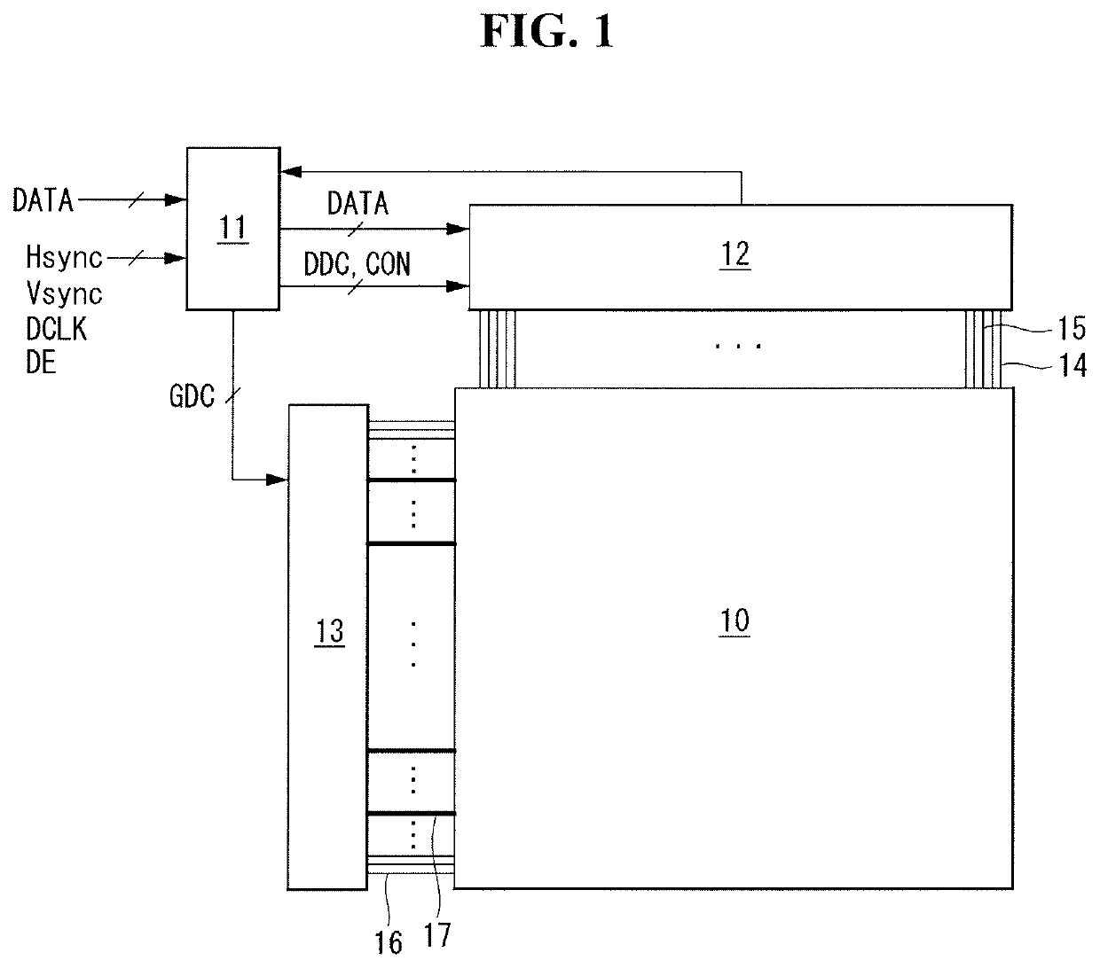
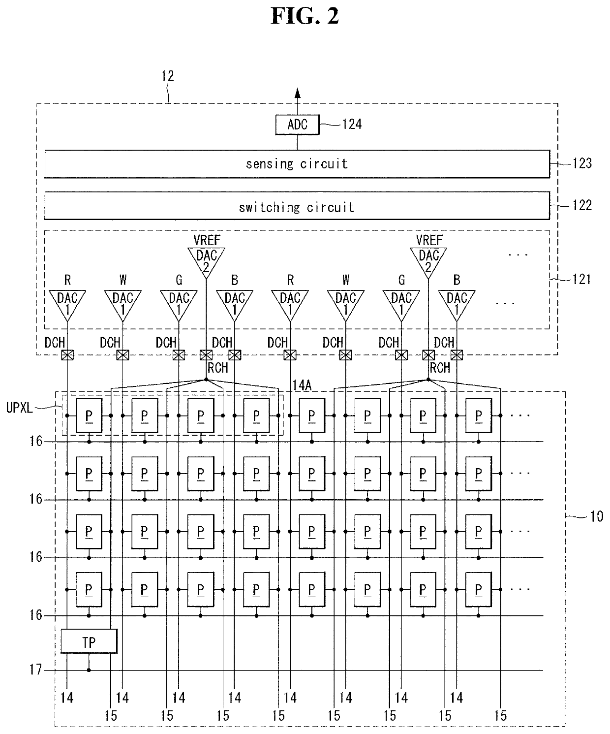
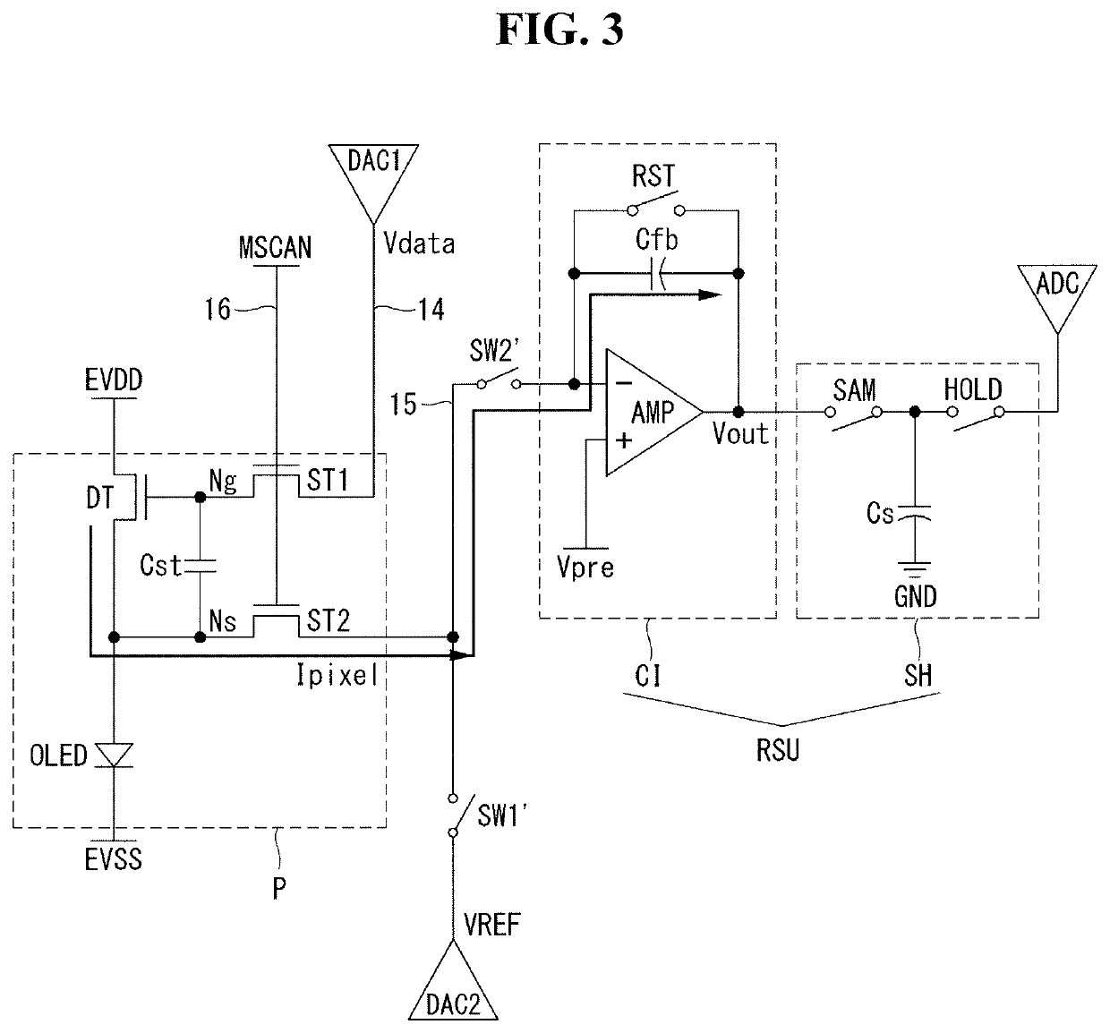
A touch sensor-integrated display device includes a display panel with a pixel array divided into a plurality of touch blocks, each touch block having a plurality of pixels for displaying an input image and at least one touch pixel for sensing touch input; a data drive circuit that applies a charging voltage to the touch pixel in each touch block through a touch sensing line and then senses an electrical charge discharged from the touch pixel and outputs the sensing result as a touch sensing value, wherein a signal line commonly connected to the pixels and the touch pixel in each touch block is used as the touch sensing line; and a timing controller that detects touch input based on the touch sensing value.

Description

[0001]This application claims the priority benefit of Korean Patent Application No. 10-2017-0117460 filed on Sep. 13, 2017 in the Republic of Korea, which is incorporated herein by reference for all purposes as if fully set forth herein.BACKGROUND OF THE INVENTIONField of the Invention[0002]The present invention relates to a touch sensor-integrated display device and a method for driving the same.Related Art[0003]Touch sensor technology is used to allow users to input information by directly touching the screen with a finger or pen or moving it near the screen while viewing the display devices of home appliances or information and communication equipment. Touch sensors are simple to use, have less malfunctions, and enable the user to input data without using an input device. In addition, the touch sensor can be applied to various display devices because it enables the user to operate it quickly and easily through contents displayed on the screen.[0004]Touch sensors can be implemente...

Claims


Application Information

Patent Timeline
Patent Type & Authority Patents(United States)
IPC IPC(8): G06F3/044G06F3/041G09G3/3275G09G3/3266G09G3/3233G09G3/3291
CPCG06F3/044G06F3/0412G06F3/04166G09G3/3233G09G3/3266G09G3/3275G09G3/3291G09G2300/0861G09G2310/08G09G2354/00G06F3/0416
Inventor KIM, TAEGUNGKIM, KYUNGROKNOH, JUYOUNG
Owner LG DISPLAY CO LTD
Learn More