Eureka AIR delivers breakthrough ideas for toughest innovation challenges, trusted by R&D personnel around the world.

Osmotic concentration of produced and process water using hollow fiber membrane

a technology of hollow fiber membrane and water, which is applied in the field of water treatment, can solve the problems of large overall footprint, large interconnection pipework, and reduced salinity of water discharged to the ocean by seawater desalination plants, and achieve the effect of reducing volume, reducing salinity or total dissolved solids (tds) and reducing the salinity of brin

Active Publication Date: 2021-05-25
CONOCOPHILLIPS CO
View PDF15 Cites 5 Cited by
  • Summary
  • Abstract
  • Description
  • Claims
  • Application Information

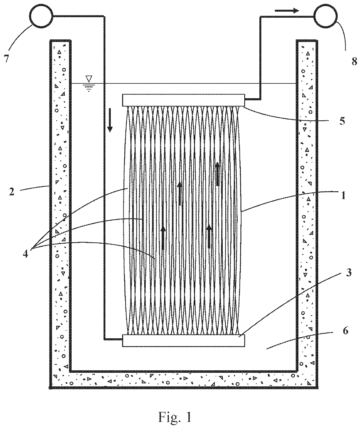
AI Technical Summary

Benefits of technology

[0010]It can be desirable for a produced or process water (“PPW”) stream, which has contaminants which make it unsuitable for anything else but disposal, to have its volume reduced (and salinity or total dissolved solids (TDS) increased) whilst at the same time reducing the salinity of the brine from, e.g., a seawater desalination plant prior to discharge to the environment. In this situation, an osmotic concentration method may be used simultaneously to reduce the volume of the PPW and the salinity of the brine by drawing water from the PPW water to the brine.
[0011]A great cost advantage may be obtained by using the immersed membrane configuration in a draw solution (saline) channel or tank which is already present, e.g. the outlet from a desalination plant. In this way, the invention saves the costs associated with pumping the draw solution into a dedicated forward osmosis unit, with associated inter-connecting pipework. Capital costs for equipment are reduced, equipment footprint, of which a major part would normally be the membrane units, is greatly reduced since the membranes are installed in pre-existing channels or tanks. When membrane servicing is required, the cassettes can be removed without any disruption to the operation of the desalination plant operation or other plant associated with the forward osmosis system. Finally, operating costs are reduced since draw solution pumping energy is eliminated.
[0013]The use of hollow fiber osmotic membranes has the advantage that they offer very high packing density and hence require only a small equipment footprint. Also, in comparison with flat sheet membranes used in immersed applications, hollow fiber membranes are much simpler to assemble into modules and do not require internal fabric spacers to keep the flat sheets apart. These factors reduce material requirements and module fabrication cost. Immersed hollow fiber membranes also have very low pressure drops for both the feed and draw solutions.
[0019]The draw solution may be seawater, saline effluent (brine) from a water desalination plant or any groundwater of sufficient salinity to provide the necessary osmotic pressure differential to achieve the desired feed volume reduction. Whilst all these are possible and advantageous, the benefits of using desalination brine include the following: (i) salinity is higher than seawater and that increases osmotic pressure differential and flux; (ii) additional pretreatment is not required since pretreatment is normally already incorporated in the desalination plant; and (iii) thermal desalination plant brine is typically warm and that improves membrane flux.
[0024]If the draw solution is efflux (brine) from a desalination plant, then it may be possible to recycle the treated brine back into the desalination plant since its salinity has been reduced by the osmotic process. Alternatively, the draw solution may be passed into the sea; the reduced salinity of the draw solution downstream of the membranes may mean its salinity is more matched to the seawater, making disposal into the sea more acceptable from an environmental standpoint.

Problems solved by technology

A separate water-related issue is reducing the salinity of water discharged to the ocean by seawater desalination plants.
If scaled up, this would involve custom built membrane vessels, considerable interconnecting pipework and a large overall footprint.
Running costs would include maintenance of this extensive plant as well as the cost of pumping two fluids.

Method used


Image

  • Osmotic concentration of produced and process water using hollow fiber membrane
  • Osmotic concentration of produced and process water using hollow fiber membrane

Examples


example 1

[0049]The objective in this design example is two-fold: i) reduce the volume of a 50 m3 / h feed stream of produced and process water by 50%, and ii) simultaneously reduce the salinity of a 100 m3 / h thermal desalination plant brine by 25%. 60 osmotic membrane fiber modules are assembled in a frame, each module arranged vertically with its inlet membrane header at the bottom and outlet membrane header at the top, the membrane headers communicating respectively with a feed header and a concentrate header on the frame. Each module comprises 1,500 fiber membranes, each membrane having a length of 1.5 m and an inner lumen diameter of 1 mm.

[0050]A detailed description of how to make the fiber membranes can be found in the Wang article, full details of which are cited above, together with U.S. Pat. No. 8,181,794 (McGinnis et al.). Briefly, the fibers are made of a polyamide membrane separation layer as described in the Wang article on a polyethylene terephthalate support layer on a polypropy...


PUM

PropertyMeasurementUnit
osmotic pressureaaaaaaaaaa
lengthaaaaaaaaaa
lengthaaaaaaaaaa

Abstract

The invention relates to a method and apparatus for treatment of produced or process water from hydrocarbon production to reduce the volume of the produced or process water while simultaneously reducing the salinity of a highly saline stream, for example, the brine from a seawater desalination plant. The method includes causing a feed stream comprising produced or process water to flow through the lumen of a hollow fiber osmotic membrane 4 which is immersed in an open channel 2 or tank of flowing draw solution 6 which has high salinity. In this way, water from the feed stream is drawn through the osmotic membrane 4 by an osmotic pressure differential caused by the difference in salinity between the feed stream and the draw solution 6.

Description

CROSS-REFERENCE TO RELATED APPLICATIONS[0001]This application is a non-provisional application which claims benefit under 35 USC § 119(e) to U.S. Provisional Application Ser. No. 62 / 353,422 filed Jun. 22, 2016, entitled “OSMOTIC CONCENTRATION OF PRODUCED AND PROCESS WATER USING HOLLOW FIBER MEMBRANE” which is incorporated herein in its entirety.FIELD OF THE INVENTION[0002]This invention relates to the treatment of water in oil and gas production to reduce the volume of water for disposal and / or to modify salinity.BACKGROUND OF THE INVENTION[0003]In the extraction of hydrocarbons from the earth, water is often extracted concurrently with the hydrocarbons (“produced water”). Sources of the water include naturally-occurring formation water and water injected into the formation from certain types of treatment operations such as secondary operations for production enhancement (e.g. steam or water floods, formation stimulation, etc.).[0004]This water often contains impurities and although...

Claims


Application Information

Patent Timeline
Patent Type & Authority Patents(United States)
IPC IPC(8): C02F1/44B01D61/00B01D63/04B01D69/08C02F103/08
CPCC02F1/445B01D61/002B01D63/04B01D69/081B01D2315/06B01D2317/022C02F2103/08Y02A20/131B01D61/0022B01D61/0021
Inventor JANSON, ARNOLDADHAM, SAMERMINIER-MATAR, JOELHUSSAIN, ALTAFSANTOS, ANA M.
Owner CONOCOPHILLIPS CO
Why Eureka
Eureka Blog
Learn More