
Bone defect repair apparatus and method

a bone defect and repair method technology, applied in the field of bone defect repair apparatus and methods, can solve problems such as pain, hypermobility or instability, and compensatory hyperextension of mtp and dip joints

Active Publication Date: 2021-05-11
ZIMMER INC
View PDF111 Cites 1 Cited by
  • Summary
  • Abstract
  • Description
  • Claims
  • Application Information

AI Technical Summary

Benefits of technology

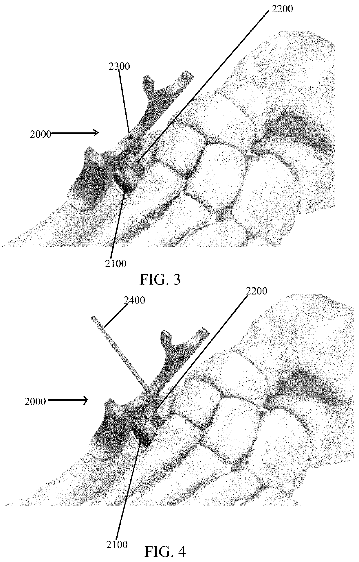
The present invention provides an orthopedic surgery instrument set for placing an implant into the medial cuneiform of the foot. The instrument set includes a targeting guide, a post, and a depth probe. The targeting guide has a body and two paddles for insertion between the medial cuneiform and the first and second metatarsals of the foot, and a bore for receiving a k-wire. The post has a cylindrical shape with multiple threaded bores, connectable to the targeting guide, that can rotate around the longitudinal axis of the post. The post also has a plug for connection to it. The depth probe has a distal tip that measures the distance between the surface of the bone and the back of the targeting guide to determine the ideal length of screw needed for the surgery. Overall, this invention provides a more efficient and precise toolset for foot surgery procedures.

Problems solved by technology

When this joint has too much looseness or movement, the condition is known as hypermobility or instability.
Progressive PIP joint flexion deformity typically leads to compensatory hyperextension of the MTP and DIP joints.
Pain occurs due to rubbing of the prominence against the patient's shoe.
However, when the deformity is fixed, PIP fusion or joint replacement is often required.
With all current implants, placement is critical because, when mounted, there is no adjustability in the angle of flexion between the two cut bones to be joined.

Method used


Image

  • Bone defect repair apparatus and method
  • Bone defect repair apparatus and method
  • Bone defect repair apparatus and method

Examples


Embodiment Construction

[0050]The present invention will be discussed hereinafter in detail in terms of various exemplary embodiments according to the present invention with reference to the accompanying drawings. In the following detailed description, numerous specific details are set forth in order to provide a thorough understanding of the present invention. It will be obvious, however, to those skilled in the art that the present invention may be practiced without these specific details. In other instances, well-known structures are not shown in detail in order to avoid unnecessary obscuring of the present invention.

[0051]Thus, all of the implementations described below are exemplary implementations provided to enable persons skilled in the art to make or use the embodiments of the disclosure and are not intended to limit the scope of the disclosure, which is defined by the claims. As used herein, the word “exemplary” or “illustrative” means “serving as an example, instance, or illustration.” Any imple...


PUM


Abstract

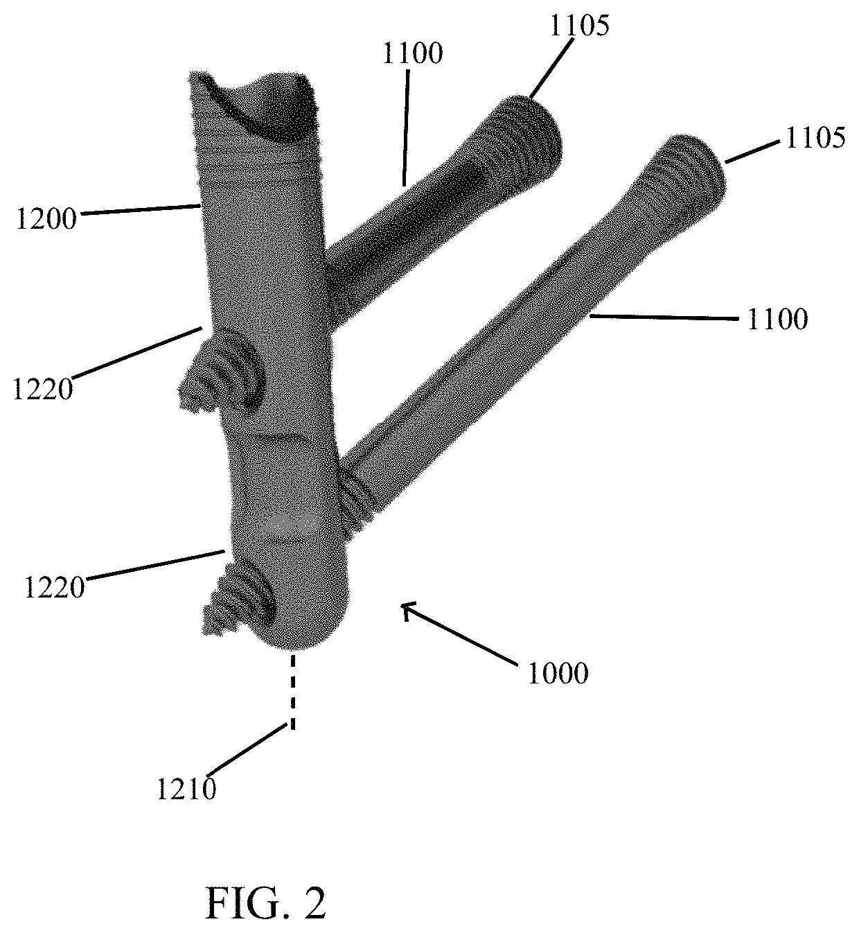
An orthopedic instrument assembly for placing an implant into a medial cuneiform of a foot, the assembly includes a targeting guide having a body with an elongated linear base. A threaded rack is disposed along the elongated linear base. A compression-distraction frame pre-compresses the joint prior to placement of a joint fixation element. The compression-distraction frame is translatably connected to the rack of the guide body base. The compression-distraction frame is releasably, statically connectable to a first metatarsal bone and a post. The post has a generally cylindrical shape and a longitudinal axis, and has a plurality of threaded cylindrical bores disposed therethrough at predefined angles relative to the longitudinal axis. The post is releasably, statically connectable to the targeting guide.

Description

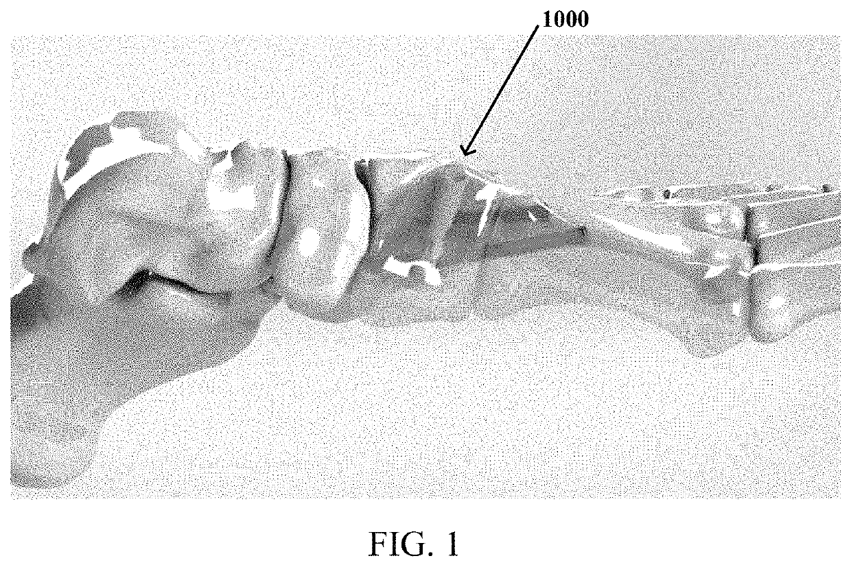
CROSS-REFERENCE TO RELATED APPLICATIONS[0001]This application is related to U.S. Pat. No. 9,603,640, Ser. No. 13 / 982,152, entitled “Lower Extremity Fusion Devices and Methods”, U.S. Pat. No. 9,662,221, Ser. No. 13 / 982,124, entitled “Upper Extremity Fusion Devices and Methods, and U.S. Patent No. 2017 / 0216043, Ser. No. 15,488,903, entitled “Upper Extremity Fusion Devices and Methods”, the entire disclosures of which are incorporated herein by reference.BACKGROUNDField of the Invention[0002]This application relates to apparatuses, devices, and methods for joining bones.Description of the Related Art[0003]Hallux valgus is the medical term for a bunion. The first tarsal-metatarsal (TMT) joint is an important joint at the inner part of the middle of the foot. The two bones that meet to form this joint are the first metatarsal and medial cuneiform bones. When this joint has too much looseness or movement, the condition is known as hypermobility or instability. When this joint becomes hype...

Claims


Application Information

Patent Timeline
Patent Type & Authority Patents(United States)
IPC IPC(8): A61B17/88A61B17/86A61B17/56A61B17/90A61B17/84A61B17/17A61B17/68A61B90/00
CPCA61B17/8872A61B17/8625A61B17/1775A61B17/848A61B17/8875A61B2017/565A61B2017/681A61B2017/90A61B2090/062A61B17/68A61B17/863A61B90/94A61B2090/3937A61B17/90
Inventor SCHLOTTERBACK, RYANDENHAM, GREGPEPPER, JOHN
Owner ZIMMER INC
Learn More