
Dynamic display system and method for customizing a controller in a display system

a display system and dynamic display technology, applied in the field of dynamic display systems and methods and apparatus for customizing the controller in the display system, can solve the problems of unbalanced conventional displays, excessive information, and limited information processing capacity of people using display devices, so as to improve cognitive bandwidth, improve performance in sports, and improve the effect of speed and better training

Active Publication Date: 2021-04-27
MASSACHUSETTS INST OF TECH
View PDF5 Cites 0 Cited by
  • Summary
  • Abstract
  • Description
  • Claims
  • Application Information

AI Technical Summary

Benefits of technology

This approach provides instantaneous feedback and allows for on-the-fly adjustments, improving cognitive bandwidth and enabling dynamic displays that adapt to individual capacity changes, enhancing performance in various applications such as sports, law enforcement, and military.

Problems solved by technology

The amount of information a person can process from a display, such as a computer display, head-up display, head mounted display, or television monitor, can be limited because conventional displays do not account for cognitive capacity limits in the person's visual hemispheres.
Often, conventional displays are unbalanced or present too much information.

Method used


Image

  • Dynamic display system and method for customizing a controller in a display system
  • Dynamic display system and method for customizing a controller in a display system
  • Dynamic display system and method for customizing a controller in a display system

Examples


example 1

ne Device

[0092]FIG. 6 illustrates an example system or kit 600 including a mobile device, e.g., smart phone, 601 and a wearable detector 630 according to an example embodiment. The smart phone device 601 includes a display device 602, e.g., a touch screen display, to display a visual stimulus 608. A built-in camera 618 can acquire images (e.g., video images) 619 of the subject 604, which can be used to identify the position and orientation of the subject's eyes to monitor eye gaze 622 of the subject. The detector 630, which is illustrated as a head mounted device, can include one or more sensors 636 to measure brain activity of the subject's left and right hemispheres 632. The detector 630 and mobile device 601 can each include a wireless communication interface to communicate, such as via Bluetooth, WiFi, or other wireless communication protocol. Each of the detector 630 and mobile device 601 can in turn communicate wirelessly with a base station (not shown). The base station can i...

example 2

isplay

[0093]FIG. 7 illustrates a display system 700 employed in a vehicle 701 according to an example embodiment. The system includes a head-up display (HUD) 702 to display information, such as a visual stimulus 708 or other visual representations. The vehicle 701 can be a passenger vehicle, a truck, a racecar, or other vehicle where monitoring of the driver's cognitive capacity may be desired. A driver (not shown) can wear a brain activity detector, such as detector 630 shown in FIG. 6 or EEG sensor caps 1000, 1020 illustrated in FIGS. 10A and 10B. A gaze monitor 718, which can be embedded in the rear view mirror as shown, is configured to monitor the driver's eye gaze. The system 700 can use the brain activity measured from the driver to adjust the information being displayed by the HUD 702. The system can use the measured brain activity and information about the monitored eye gaze to assess current level of cognitive function of the driver and, as a result of the assessment, take...

example 3

vice

[0094]FIG. 8 illustrates a system 800 for assessing a concussion or other brain injury. The system includes a football-style helmet device 801 with integrated display device 802 and brain activity detector 830. The display device 802 can display one or more stimuli 808 to subject 804 wearing the helmet device 801. As illustrated, the display device 802 can include a projector 803 to project an image onto a visor of the helmet device, thereby displaying a stimulus 808 to the subject 804. A gaze monitor 818 can be included in the helmet device to monitor the subject's eye gaze while the subject is viewing the stimulus 808 displayed. The detector 830 can include one or more sensors 836, 838 to detect brain activity of the subject's left and right hemispheres. The sensors 836, 838 can be EEG electrodes embedded in the helmet device 801. The helmet device can further include a controller 850 in communication with the display device 802 and a processor 852 in communication with the co...


PUM


Abstract

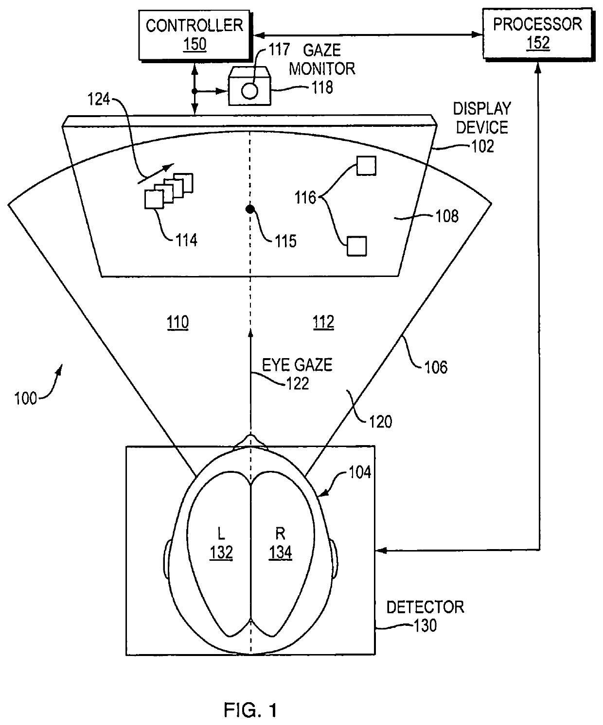
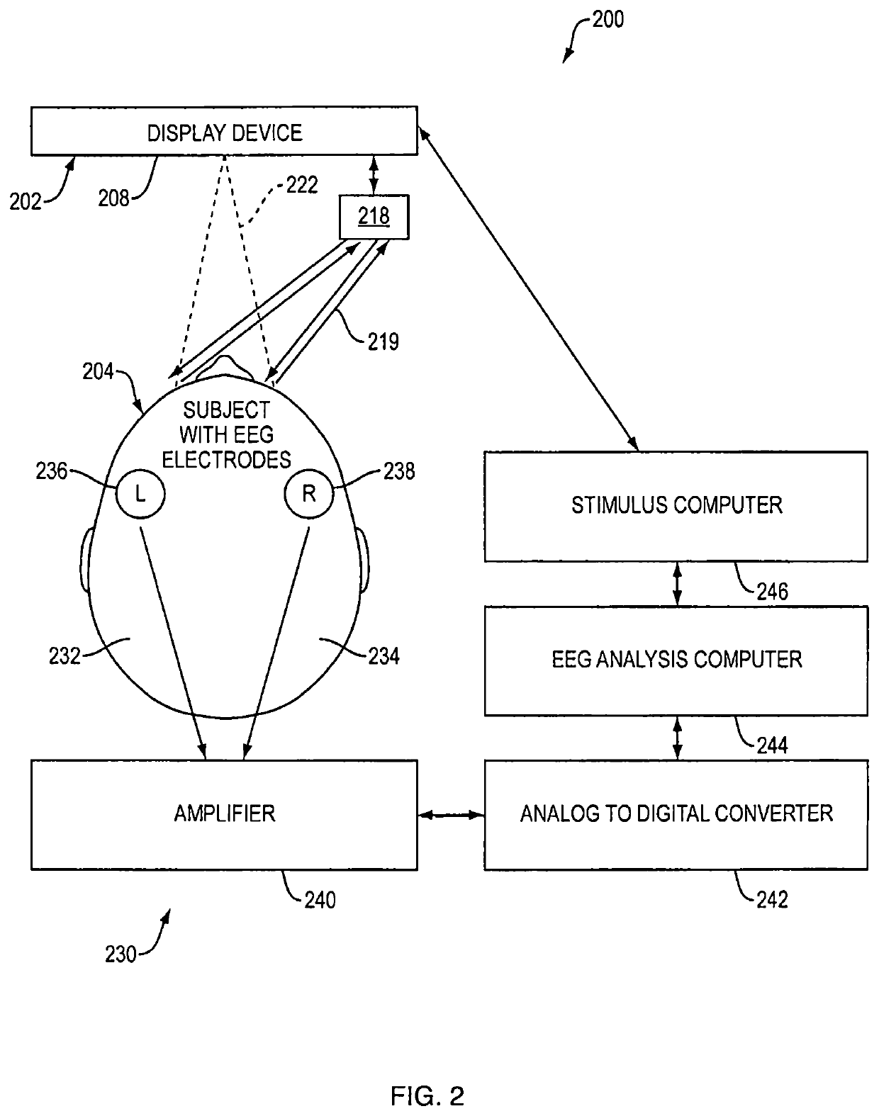
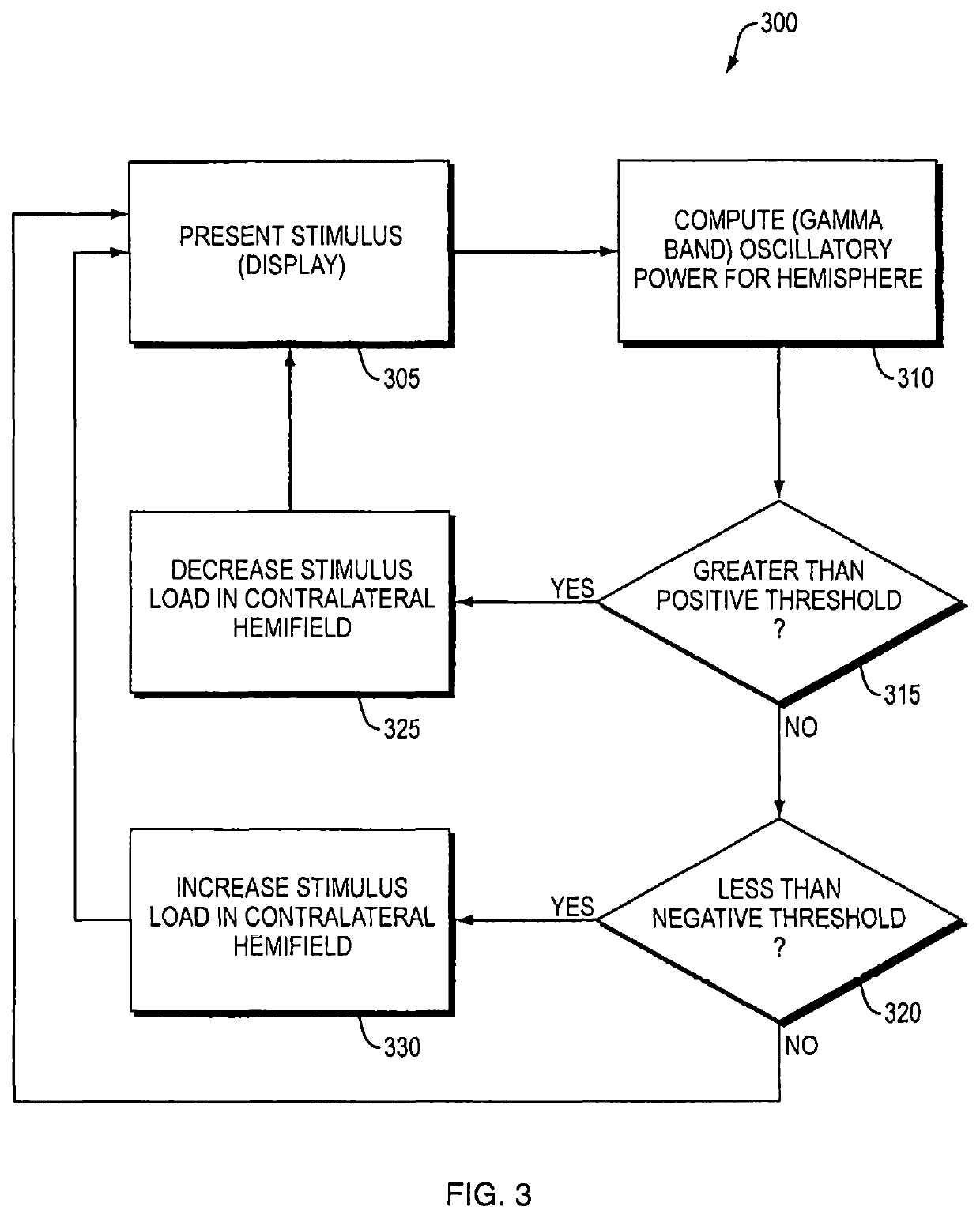
A method, or corresponding dynamic display system, for customizing a controller of a display system includes presenting a visual stimulus to a subject at at least one known location relative to the subject's eye gaze; measuring brain activity of the subject's left and right brain hemispheres in response to the subject's viewing of the stimulus; processing the measured brain activity to determine a frequency-dependent metric of the measured brain activity; assessing independent cognitive capacities of the subject's left and right brain hemispheres based on the frequency-dependent metric; and adjusting a function of the controller in the display system according to the assessed independent capacities, such as by adjusting the function to change a stimulus load in a visual hemifield according to the brain activity in the contralateral brain hemisphere. Example applications include head-up display (HUD), augmented reality (AR) or virtual reality (VR) display systems, and brain injury assessment systems.

Description

RELATED APPLICATION(S)[0001]This application claims the benefit of U.S. Provisional Application No. 62 / 376,132, filed on Aug. 17, 2016. The entire teachings of the above application are incorporated herein by reference.GOVERNMENT SUPPORT[0002]This invention was made with Government support under Grant No. RO1 MH091174 awarded by the National Institutes of Health. The Government has certain rights in this invention.BACKGROUND[0003]The amount of information a person can process from a display, such as a computer display, head-up display, head mounted display, or television monitor, can be limited because conventional displays do not account for cognitive capacity limits in the person's visual hemispheres. Often, conventional displays are unbalanced or present too much information.SUMMARY OF THE INVENTION[0004]Embodiments of the present invention generally relate to display systems and methods and apparatus for customizing a controller in a display system. Embodiments include technolog...

Claims


Application Information

Patent Timeline
Patent Type & Authority Patents(United States)
IPC IPC(8): A61B3/00G09B19/00A61B5/055A61B5/0476A61B5/00A61B3/10A61B5/0484A61B8/06A61B8/08A61B5/04A61B5/048
CPCA61B3/0041A61B3/10A61B5/0059A61B5/0476A61B5/04842A61B5/055A61B5/6801A61B5/7278A61B5/048A61B5/04009A61B8/06A61B8/0816G09B19/00A61B5/246A61B5/374A61B5/378A61B5/369
Inventor MILLER, EARL KEITHBUSCHMAN, TIMOTHY JOSEPHKORNBLITH, SIMON JOHN
Owner MASSACHUSETTS INST OF TECH
Learn More