Liquid manure hose coupler

a liquid manure hose and coupler technology, applied in the direction of hose connections, sleeves/socket joints, flanged joints, etc., can solve the problems of large hose length, large diameter, and large hose length, and achieve the effect of convenient field installation, increased coupling force to the hose, and reliable securing a pair of hose sections

Active Publication Date: 2021-04-13
PRINCIPLE CNC MFG INC
View PDF48 Cites 0 Cited by
  • Summary
  • Abstract
  • Description
  • Claims
  • Application Information

AI Technical Summary

Benefits of technology

[0018]A first object of the invention is to provide a liquid manure drag hose coupler for use in agricultural operations where manure is used as a beneficial, nutrient rich soil treatment for the crop lands, to couple drag hoses that run between a liquid manure storage tank and a manure spreader. A second object of the invention is to provide a liquid manure drag hose coupler capable of reliably securing a pair of hose sections together. Another object of the present invention is to provide a liquid manure drag hose coupler that may be readily installed in the field, even when exposed to dirt and debris, and yet will subsequently operate reliably. A further object of the invention is to provide a liquid manure drag hose coupler that will most preferably be capable of a greater coupling force to the hose than the hose can intrinsically withstand. Yet another object of the present invention is to provide a liquid manure drag hose coupler that is compatible with newer, heavier, and more advanced hoses that can withstand more abrasion and pressure. An additional object of the present invention is to provide a liquid manure drag hose coupler having minimal protrusions, so as to not interfere with or harm the hose during winding and unreeling upon a large spool, and which will also create less drag and interference with obstacles when dragged about the field.

Problems solved by technology

Finally, as apparent from the name, the drag hose will be dragged about the crop land behind the tractor and manure spreader, and so will be exposed to abrasion with the earth and potential entanglement with any obstacles.
As may be appreciated, this large diameter, very long, durable, high pressure hose is also necessarily very heavy.
In addition, while standard hose lengths may extend up to a few hundred yards, there are many situations that require far greater hose lengths.
However, in other instances a hose may leak or burst during use.
This is because, as the hose is dragged around the land, the hose will be under great tension.
Owing to the large hose diameter, a large amount of liquid may be contained within the hose, adding substantially to the total weight of the hose.
In this case, the couplers may be exposed to dirt and debris, and yet must still be readily installed and subsequently operate reliably.
In the event of a failure, the failure will then occur in the form of a tear in the hose, rather than a separation between the coupler and hose.
The latter separation between coupler and hose could dangerously propel the hard coupler through the air.
Unfortunately, the hose wall thickness is greater than prior art clamps were designed for, the hose exterior may fabricated from materials that are less prone to abrasion, and the hoses themselves fail at greater forces and pressures.
As a result, many of the prior art couplers are unable to provide a desired strength of connection.
Unfortunately, couplers that have been developed heretofore have metal portions that protrude beyond the outer diameter of the hose, and in many cases these protrusions are relatively abrupt and even sharp.
Unfortunately then, the couplers themselves can harm the hose during winding and unwinding.
In addition, the protrusions will also create somewhat more drag and interference with obstacles in the field.

Method used


Image

  • Liquid manure hose coupler
  • Liquid manure hose coupler
  • Liquid manure hose coupler

Examples


Embodiment Construction

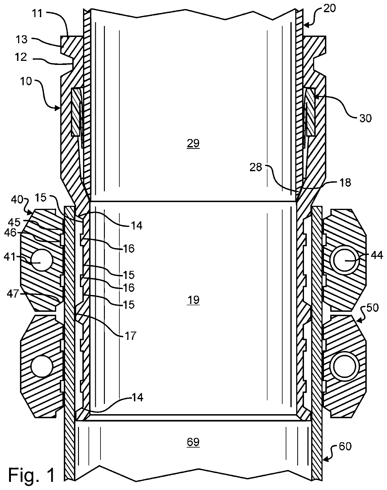
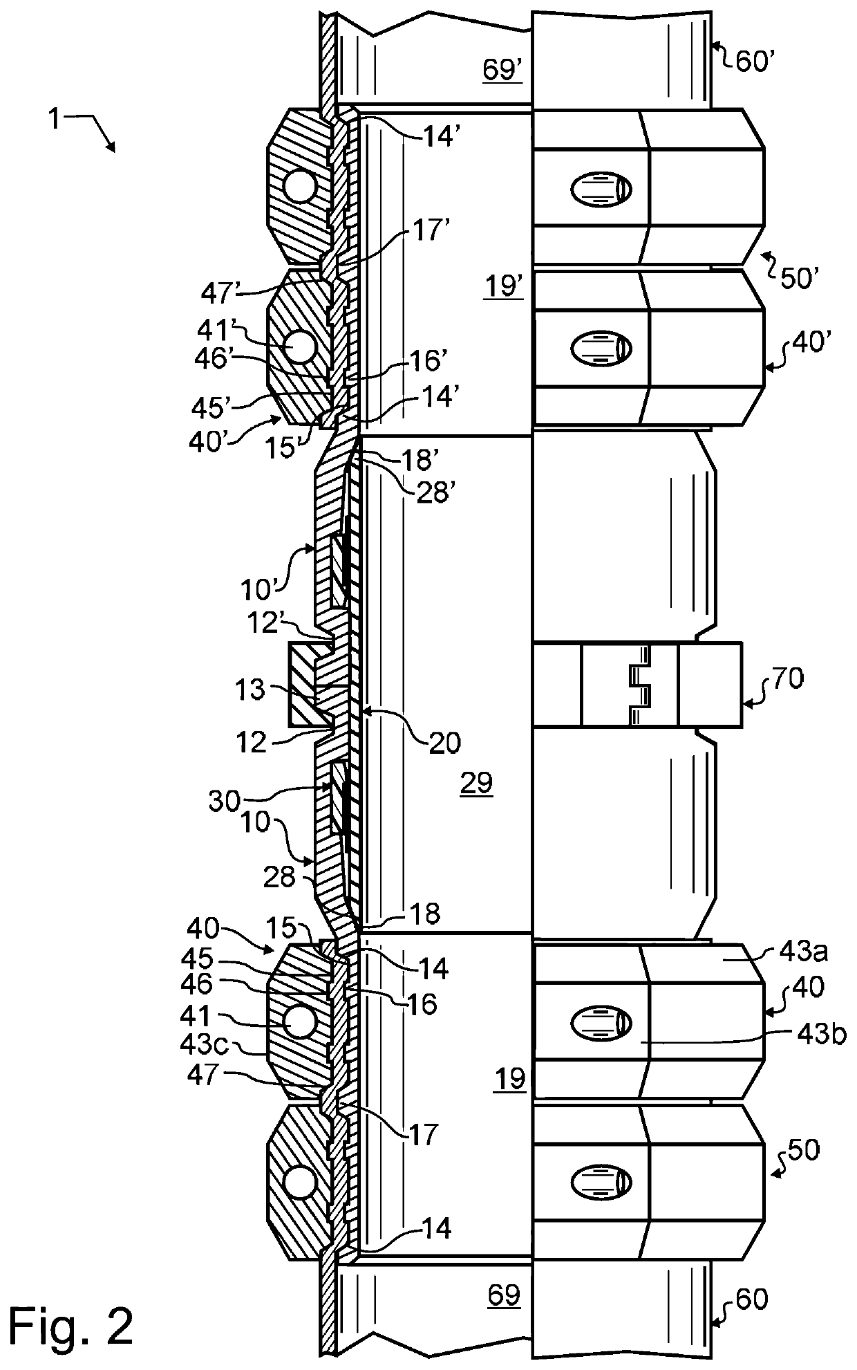
[0023]Manifested in the preferred embodiment, the present invention provides a hose coupler 1 having improved clamping features. One coupler end 10 of preferred embodiment liquid manure hose coupler 1 is illustrated in FIG. 1 from a sectional view, in combination with a prior art drag hose 60. The fully assembled hose coupler 1 is illustrated in FIG. 2, providing a pair of coupler ends 10, 10′ that are coupled together. With reference to these Figures, a first end face 11 terminates preferred embodiment liquid manure hose coupler end 10 distal to hose 60. Adjacent to first end face 11 is a clamp ridge 13, and next to that but somewhat more distal to first end face 11 is a clamp groove 12. As will be described in greater detail herein below, clamp groove 12 provides an engagement for a clamp 70, and allows preferred embodiment liquid manure hose coupler end 10 to be clamped to a second like preferred embodiment liquid manure hose coupler end 10′.

[0024]In the vicinity of clamp groove ...


PUM


Abstract

A hose coupler optimally configured for use with a liquid manure drag hose has a pair of hose coupler ends that are joined using a hose coupler having minimal protrusions and diameter. Each of the hose coupler ends is provided with a plurality of ribs and grooves. These ribs and grooves are arranged to mate with corresponding grooves and ribs formed in a collar. For each hose coupler end, a pair of collars are preferably used to secure a hose thereto. The ribs and grooves are preferably configured to secure the hose and distribute tension applied to the hose throughout the coupler end, while ensuring that the hose wall integrity is maintained. The resulting coupler is compatible with heavier drag hose, will not interfere with or harm the hose during winding and unreeling, and will produce less drag and be less likely to produce interference with obstacles in the field.

Description

CROSS REFERENCE TO RELATED APPLICATIONS[0001]The present application claims the benefit of United States provisional patent application 62 / 528,099 filed Jul. 1, 2017 of like title and inventorship, the teachings and entire contents which are incorporated herein by reference.BACKGROUND OF THE INVENTION1. Field of the Invention[0002]This invention pertains generally to pipe joints or couplings, and more particularly to a hose coupler adapted to securely, safely, and compactly couple together high strength drag hose such as used in liquid manure application.2. Description of the Related Art[0003]In agricultural operations that include both livestock and crop lands, manure which is a waste by-product from livestock can be used as a beneficial, nutrient rich soil treatment for the crop lands. On larger farms, the manure may be stored in a liquid manure storage tank, lagoon, or the like. To apply the manure to the land, the manure will be pumped from the storage tank through a semi-flexib...

Claims


Application Information

Patent Timeline
Patent Type & Authority Patents(United States)
IPC IPC(8): F16L21/02F16L23/04F16L21/06F16L33/02
CPCF16L21/02F16L21/065F16L23/04F16L33/023F16L33/23
Inventor TOTUSHEK, DENNIS L.SCHUG, DANIEL W.
Owner PRINCIPLE CNC MFG INC
Why Eureka
Try Eureka