
Dynamic antenna array pattern switching in wireless systems

a dynamic pattern and wireless technology, applied in the field of wireless device/system connectivity problems, can solve the problems of affecting power consumption, footprint, operation time, power consumption,

Active Publication Date: 2021-04-06
CYPRESS SEMICON CORP
View PDF21 Cites 2 Cited by
  • Summary
  • Abstract
  • Description
  • Claims
  • Application Information

AI Technical Summary

Benefits of technology

The patent describes using dynamic switching techniques to improve the precision of estimating the direction of a signal, reduce power consumption, and make the system faster. This involves changing the pattern of the antennas to better match the needs of the system.

Problems solved by technology

Existing designs and techniques for estimating AoA or AoD face various challenges such as backward compatibility issues and demands to increase accuracy and to reduce cost, footprint, operation time, and power consumption.
Not only do the number of transceivers impact the Bill-Of-Materials (BOM) and footprint of the wireless device, but there is a linear relationship between the number of antennas and complexity, which impacts power consumption, among other performance targets.
Some wireless devices may use switching circuitry to couple its single transceiver (e.g., single-radio) to multiple antennas, one at a time, which can result in reduced BOM, footprint, complexity, and overall power consumption (e.g., compared to multi-radio solutions).
These systems may have the complexity associated with one antenna, plus a small overhead for the switching control.
In embodiments, CTE may be an limited resource.
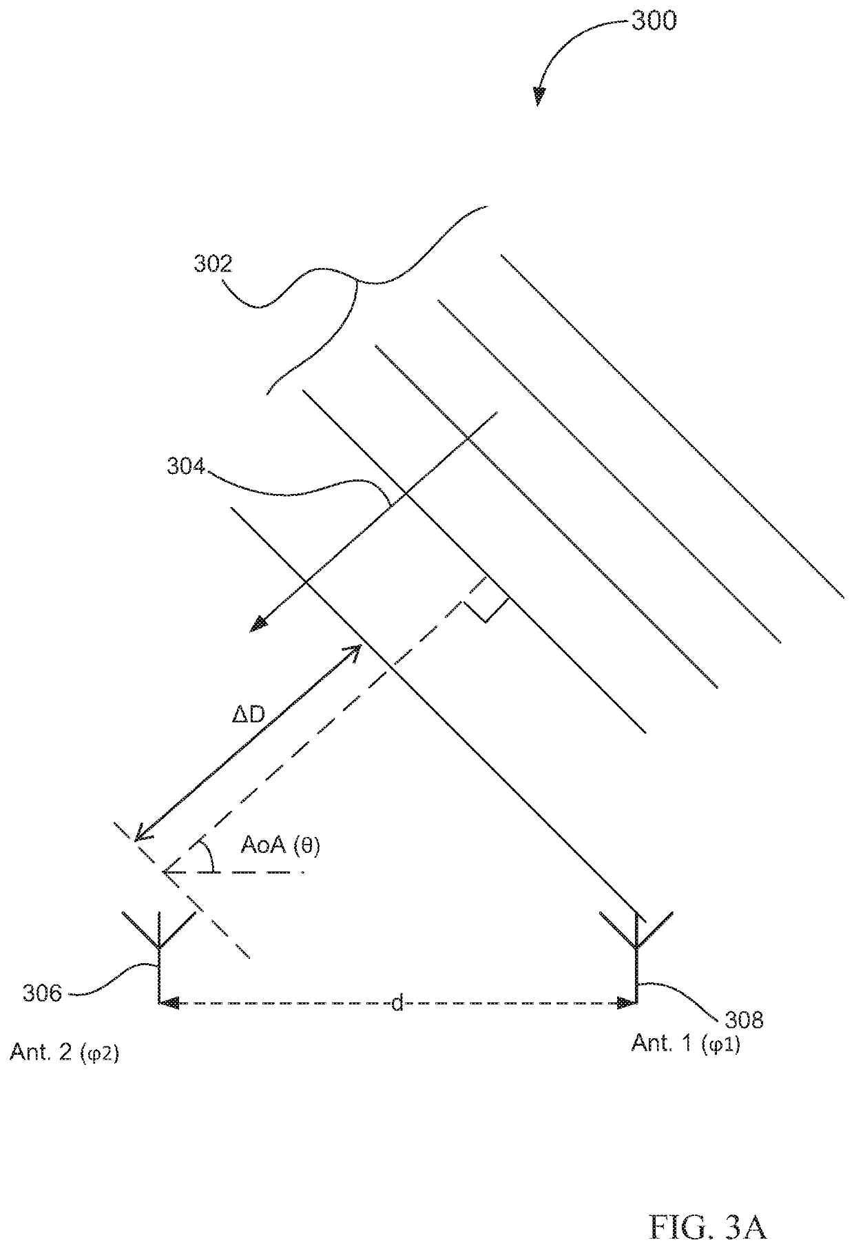
2 and 3 may have a shorter distance between them, and the short distance may adversely affect its efficiency and sensitivity in directional estimation.
While directional resolution may be improved by having more active antennas in an array and increased physical distance among the antennas, in some applications, they may not be feasible due to restraint in power consumption, BOM and footprint.
In addition, not all antennas in an array may contribute equally in response to RF signals coming in at different angles.
3 and 4 even generate directional estimation data that may adversely affect directional resolution of the four-antenna array.

Method used


Image

  • Dynamic antenna array pattern switching in wireless systems
  • Dynamic antenna array pattern switching in wireless systems
  • Dynamic antenna array pattern switching in wireless systems

Examples


Embodiment Construction

[0017]The following description sets forth numerous specific details such as examples of specific systems, components, methods, and so forth, in order to provide a good understanding of several embodiments of the subject matter. It will be apparent to one skilled in the art, however, that at least some embodiments may be practiced without these specific details. In other instances, well-known components or methods are not described in detail or are presented in a simple block diagram format in order to avoid unnecessarily obscuring the techniques described herein. Thus, the specific details set forth hereinafter are merely exemplary. Particular implementations may vary from these exemplary details and still be contemplated to be within the spirit and scope of the subject matter.

[0018]Unless specifically stated otherwise, as apparent from the following discussions, it is appreciated that throughout the specification discussions utilizing terms such as “generating”, “detecting”, “proc...


PUM


Abstract

An example method of operating a device includes using a switching circuitry to a first subset of antennas from an antenna cluster, using the first subset of antennas to receive a first Bluetooth signal, generating a first directional value of the first Bluetooth signal, using a processing element to evaluate at least one antenna of the antenna cluster based at least partly on the first directional value, selecting a second subset of antennas based on evaluation, using the second subset of antennas to receive a second Bluetooth signal, and generating a second directional value of the second Bluetooth signal. Other embodiments of the device and operations thereof are also disclosed.

Description

PRIORITY[0001]The present application claims the priority and benefit under 35 U.S.C. § 119(e) of U.S. Provisional Application No. 62 / 775,012, filed on Dec. 4, 2018, which is incorporated by reference herein in its entirety.TECHNICAL FIELD[0002]The present disclosure relates generally to wireless device / system connectivity issues. More particularly, it relates to antenna array or cluster dynamic pattern switching embodiments and method of operation thereof.BACKGROUND[0003]Computing devices may communicate with each other via networks, such as wireless networks (e.g., Wi-Fi networks, Bluetooth networks, etc.). A computing device may communicate with another device (e.g., another computing device) in the wireless network by transmitting radio-frequency (RF) signals to and / or receiving RF signals from one another. Those devices within the wireless network may also utilize the transmitted / received RF signals to generate relative directional data of each other. One of the techniques is u...

Claims


Application Information

Patent Timeline
Patent Type & Authority Patents(United States)
IPC IPC(8): H04W4/80H04W64/00H04B17/318H04B17/336H04W24/10
CPCH04W4/80H04B17/318H04B17/336H04W24/10H04W64/006H04W84/18G01S3/48H04W4/02H01Q3/24
Inventor SIMILEYSKY, VICTOR
Owner CYPRESS SEMICON CORP
Learn More