Intraocular lens system

a technology of intraocular lens and lens body, which is applied in the field of intraocular lens, can solve the problems of reducing the field of view of patients, and affecting the treatment effect of patients, so as to increase the depth of focus of the system and increase the range of eccentricities

Active Publication Date: 2021-03-30
SYNEOS HEALTH INT LTD
View PDF65 Cites 6 Cited by
  • Summary
  • Abstract
  • Description
  • Claims
  • Application Information

AI Technical Summary

Benefits of technology

The patent describes a method for designing a multi-lens optical system that can create a high-quality image on the retina for patients with varying degrees of eye eccentricity. The system uses an optimization process to determine the precise values of the lens radius and asphericity, which can be adjusted to produce a similar optical performance for different angles of retinal eccentricity. Additionally, the anterior lens may have an opaque annulus to prevent blurring of the retinal image caused by light traveling around the lens.

Problems solved by technology

The most common condition affecting the macula is age-related macular degeneration (AMD)—this is also the most common cause of significant visual loss in the developed world.
Use of such devices is often restrictive because magnifying glasses are not easily portable (and require good lighting), and telescopic devices can severely reduce a patient's field of view.
Despite the problems associated with reduced visual resolution, patients with age-related macular degeneration and similar conditions affecting the central visual field may still make effective use of residual macular tissue outside the damaged fovea (sometimes referred to as the ‘preferred retinal locus’ or PRL) although this may require the patient to learn to fixate eccentrically—something that is not always easily accomplished.
Furthermore, as the disease progresses and remaining islands of functioning retina shrink in size, the location of the PRL can shift and it may become necessary to alter the path of light in the eye to take account of this.
Firstly, the prismatic effect is conferred by the diverging IOL, which lies behind the converging IOL in both instances, thereby making access difficult for the purpose of rotating the diverging IOL to target the PRL should its location change at a future date.
Secondly, the siting of an IOL in the anterior chamber is known to be associated with secondary pathology such as glaucoma and damage to the cornea of the eye.
Thirdly, the optics of such a configuration are highly dependent on the IOLs remaining a fixed distance apart, for the purposes of magnification, and at a fixed displacement perpendicular to the optical axis (in the case of the diverging lens) for the purposes of targeting the PRL so that without consideration of the optimal configuration of the IOLs in relation to one another the system has the potential to make a patient's vision even worse.
The principal disadvantages of fixing the diverging lens to the converging lens in these systems are that: 1) The arrangement may not permit the displacement of one lens in relation to the other to create the prismatic effect necessary to target the PRL (as is the case with most cylindrical one-piece designs); 2) in some instances, the prismatic effect, if achieved, may not be modifiable without replacing the implant; 3) in the case of systems where the device (or part of the device) is implanted in the capsular bag, fibrosis of the capsular bag over the implant may prevent its easy replacement or rotation should the need arise for adjustment in response to a change in the PRL; 4) the size of the implant is increased such that a larger incision in the eye is required to site it (this is associated with longer wound-healing time and increased astigmatism that may adversely affect the quality of vision).

Method used


Image

  • Intraocular lens system
  • Intraocular lens system
  • Intraocular lens system

Examples


Embodiment Construction

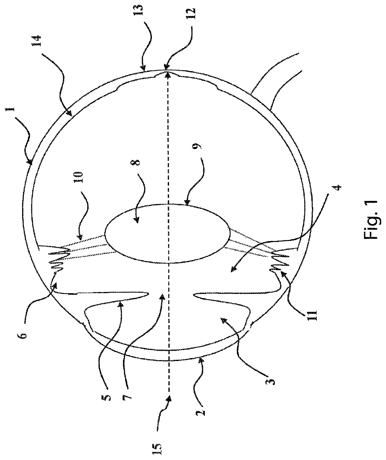
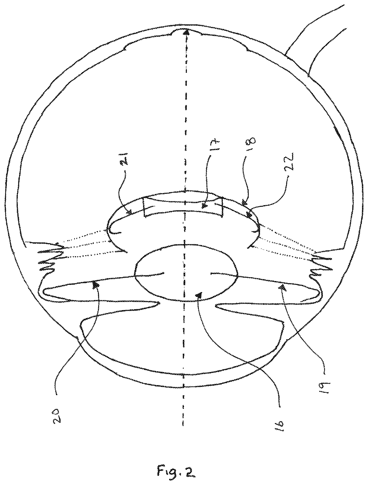
[0055]One embodiment of the present invention comprises two separate IOLs. The first is a light-converging lens shaped and sized for siting anteriorly to the second optic in the ciliary sulcus of the eye. The second is a posterior light-diverging lens shaped and sized for siting in the capsular bag. This embodiment is best employed with the IOLs sited in these positions but other embodiments allow for siting of the light-converging lens in the anterior chamber of the eye and the light-diverging IOL in the ciliary sulcus or both IOLs in the ciliary sulcus or both IOLs in the capsular bag. The IOLs are stabilized in their relative positions by means of haptics attached to or continuous with the optic of each lens and the configuration provides a magnified image in the manner of a Galilean telescope. However, in order to focus retinal images across a range of retinal eccentricities from the foveal centre the surfaces of the intraocular lenses are rendered aspherical. This sacrifices op...


PUM


Abstract

An intraocular lens system comprising at least one intraocular lens having an anterior surface and a posterior surface, wherein at least one surface of the lens is aspherical to provide for a continuum of retinal images to be focused at the retina in an area between two retinal eccentricities. The system may include an anterior light-converging intraocular lens 16 for positioning within the eye, the anterior lens having an anterior surface and a posterior surface; and a posterior light-diverging intraocular lens 17 for positioning within the eye posterior to the anterior lens, the posterior lens having an anterior surface and a posterior surface; wherein one or both surfaces of the anterior lens and / or one or both surfaces of the posterior lens are aspherical.

Description

FIELD OF THE INVENTION[0001]The present invention relates to an intraocular lens system.[0002]Throughout this application, the terms ‘lens’ and ‘optic’ are used interchangeably. It should be understood that optic refers to a refractive component of the intraocular lens.BACKGROUND[0003]The most common condition affecting the macula is age-related macular degeneration (AMD)—this is also the most common cause of significant visual loss in the developed world. AMD results in loss of the light-sensitive cells (photoreceptors), and supporting tissue at the back of the eye, in a specialised part of the retina known as the macula. The condition most often involves the very central part of the macula (the fovea), an area which enables reading and the recognition of faces. In the majority of patients with age-related macular degeneration loss of vision occurs over a number of years and the pattern of visual loss allows for the maintenance of small islands of functioning photoreceptors in the ...

Claims


Application Information

Patent Timeline
Patent Type & Authority Patents(United States)
IPC IPC(8): A61F2/16
CPCA61F2/1648A61F2/164A61F2/1613A61F2/1637A61F2/1651A61F2/1656A61F2002/169A61F2002/1683A61F2002/1689A61F2002/1696A61F2002/1699A61F2002/1681
Inventor QURESHI, MARTAL, PABLOSCOTT, ROBBIETABERNERO, JUAN
Owner SYNEOS HEALTH INT LTD
Why Eureka
Try Eureka