Scroll compressor

a compressor and crank technology, applied in the direction of machines/engines, rotary/oscillating piston pump components, liquid fuel engines, etc., can solve the problems of disadvantageous difficulty in activating compressors, etc., to reduce compression load, reduce compression load at activation, and improve compressor startability

Active Publication Date: 2021-03-09
PANASONIC INTELLECTUAL PROPERTY MANAGEMENT CO LTD
View PDF16 Cites 0 Cited by
  • Summary
  • Abstract
  • Description
  • Claims
  • Application Information

AI Technical Summary

Benefits of technology

[0013]Accordingly, at the activation of the compressor, since a gap is generated between the non-orbiting scroll and the orbiting scroll, complete compression is not achieved immediately after the activation to reduce a compression load. In this manner, the startability of the compressor can be improved.
[0014]In the scroll compressor of the present disclosure, the elastic body biases the fixed scroll and the orbiting scroll so as to separate the fixed scroll and the orbiting scroll from each other, to reduce the compression load at the activation. This can improve the startability of the compressor.

Problems solved by technology

As a result, in the case of using a single-phase motor having a small starting torque as motor 801, it is disadvantageously difficult to activate compressor 111.

Method used


Image

  • Scroll compressor
  • Scroll compressor
  • Scroll compressor

Examples


first exemplary embodiment

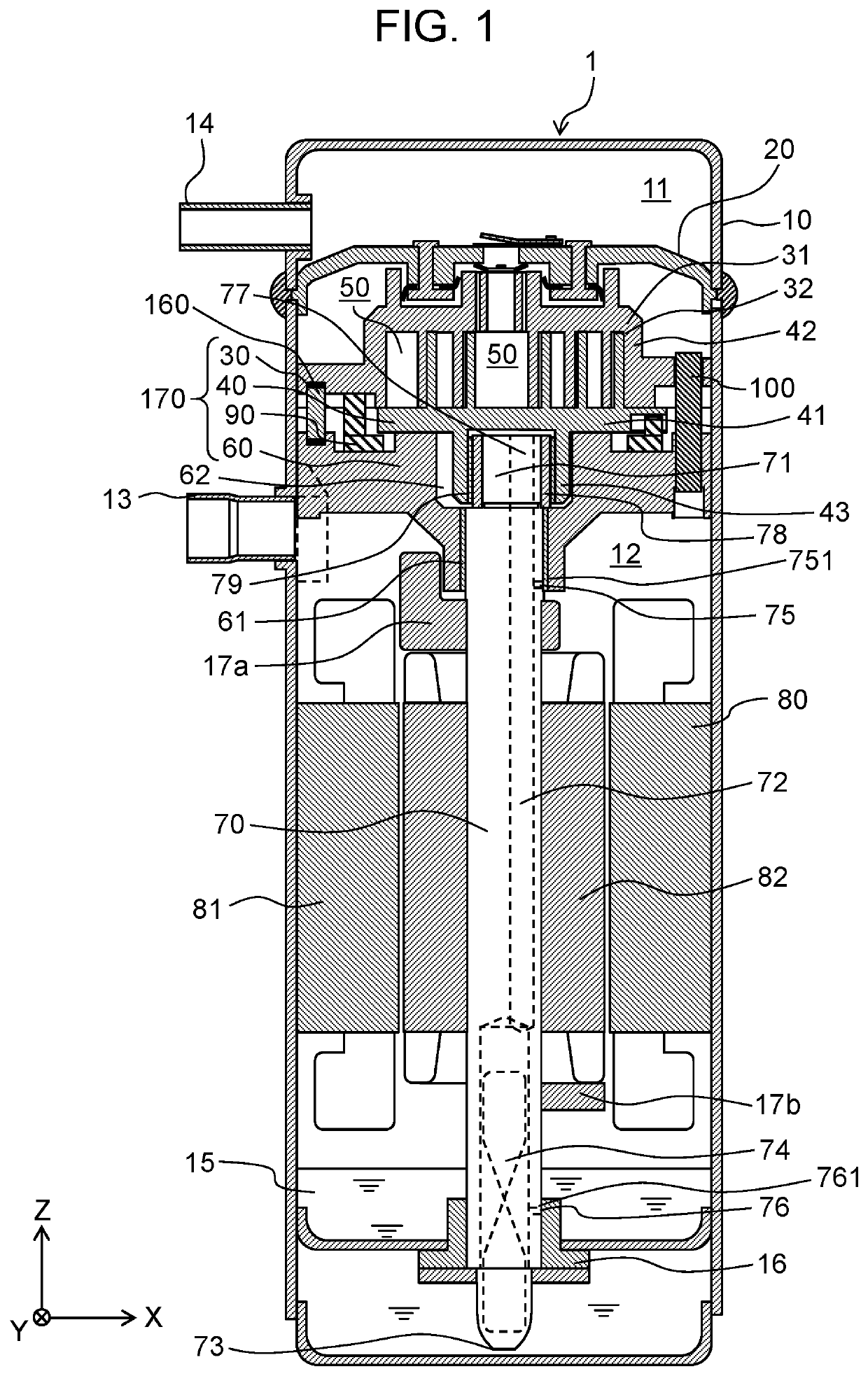
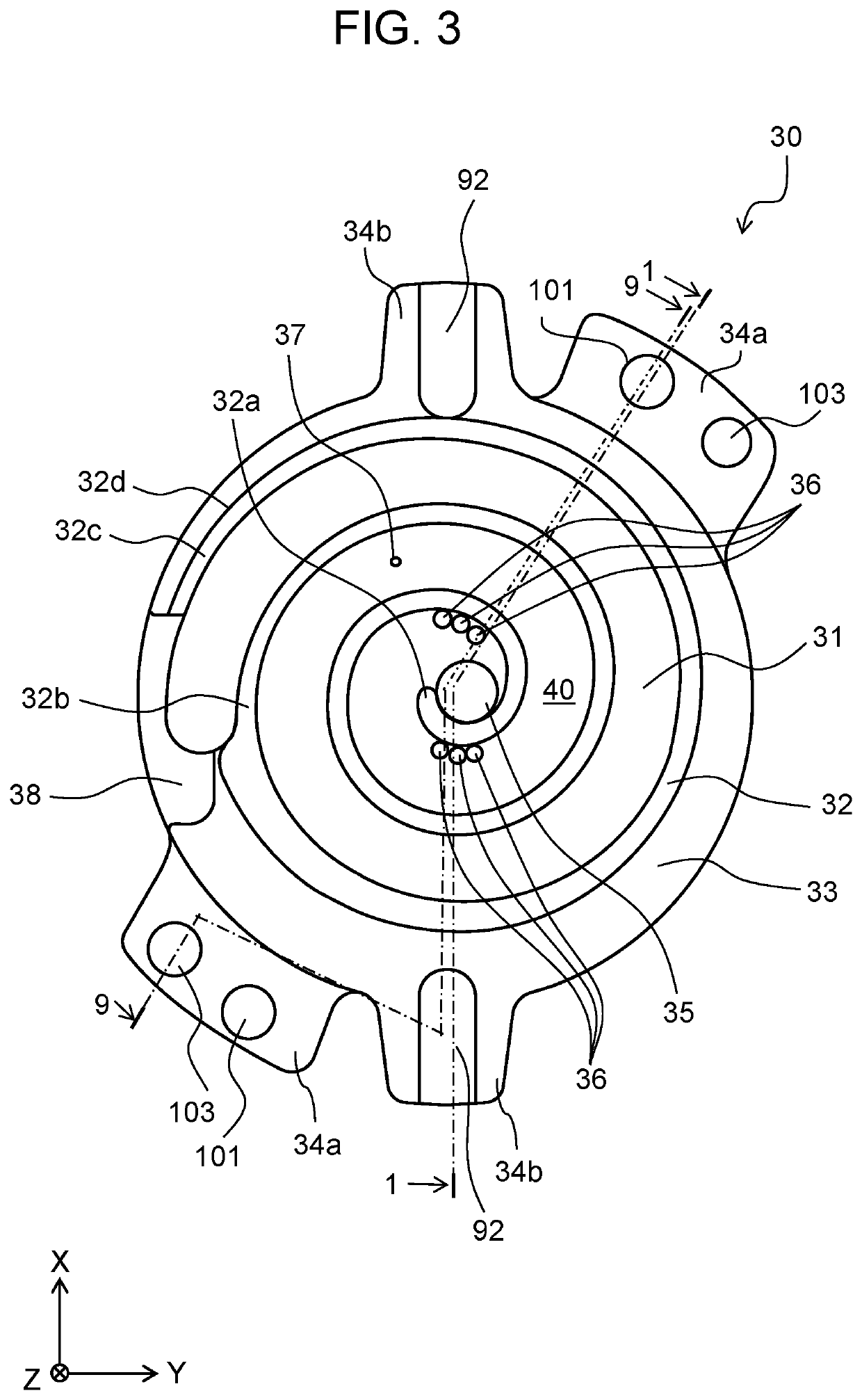
[0039]FIG. 1 is a longitudinal sectional view of a scroll compressor according to the present exemplary embodiment. FIG. 1 illustrates a cross-section taken along line 1-1 in FIG. 3. As illustrated in FIG. 1, compressor 1 includes sealed vessel 10 having a tubular shape and a longitudinal direction that is a vertical direction, as an outer shell. In this specification, the vertical direction denotes a Z-axis direction in each of FIGS. 1 to 9.

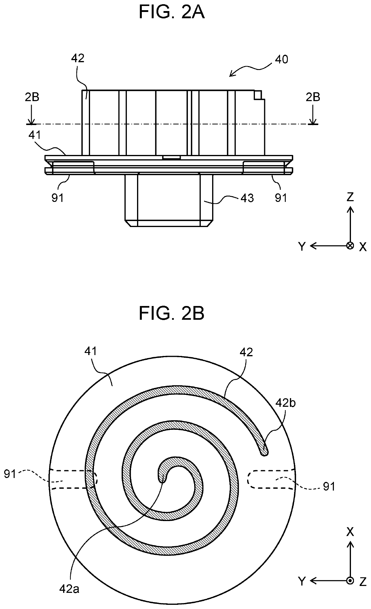
[0040]Compressor 1 is a sealed scroll compressor including compression mechanism 170 for compressing a refrigerant and motor 80 for driving compression mechanism 170, within sealed vessel 10. Compression mechanism 170 includes at least fixed scroll 30 that is a non-orbiting scroll, orbiting scroll 40, main bearing 60, and Oldham ring 90.

[0041]Partition wall 20 that vertically partitions the inside of sealed vessel 10 is provided in an upper portion of the inside of sealed vessel 10. Partition wall 20 divides the inside of sealed vessel 10 into h...


PUM


Abstract

A scroll compressor according to the present disclosure includes a partition wall that divides a sealed vessel into a high-pressure space and a low-pressure space, a non-orbiting scroll provided in the low-pressure space, an orbiting scroll that forms a compression chamber between the orbiting scroll and the non-orbiting scroll, and a rotational shaft. The scroll compressor further includes a main bearing that supports the orbiting scroll, an elastic body that biases one of the non-orbiting scroll and the orbiting scroll so as to separate the non-orbiting scroll and the orbiting scroll from each other, and a plurality of columnar members that are fixed at one ends of the columnar members and are movable at the other ends of the columnar members, and are disposed in a circumferential direction. The non-orbiting scroll or the orbiting scroll that is biased by the elastic body is movable between the partition wall and the main bearing in an axial direction of the rotational shaft. The elastic body is disposed between the plurality of columnar members in the circumferential direction.

Description

TECHNICAL FIELD[0001]The present disclosure relates to a scroll compressor.BACKGROUND ART[0002]A sealed scroll compressor including a partition wall provided within a sealed vessel, a compression mechanism having a fixed scroll and an orbiting scroll in a low-pressure space partitioned with the partition wall, and a motor that orbits the orbiting scroll has been recently known. In such a compressor, a boss of the fixed scroll is fitted into a holding hole in the partition wall. A refrigerant compressed by the compression mechanism is ejected to a high-pressure space partitioned with the partition wall via an ejection port in the fixed scroll (Refer to, for example, Patent Literature 1).[0003]In such a compressor, since the compression mechanism is disposed in the low-pressure space, during the operation of the compressor, a force is applied to the fixed scroll and the orbiting scroll so as to separate the fixed scroll and the orbiting scroll from each other.[0004]For this reason, it...

Claims


Application Information

Patent Timeline
Patent Type & Authority Patents(United States)
IPC IPC(8): F04C28/20F04C28/06F04C18/02F04C27/00F04C29/00F04C23/00
CPCF04C28/20F04C18/0215F04C18/0253F04C23/008F04C27/005F04C28/06F04C29/0021F04C2230/60F04C2240/50F04C2240/805
Inventor YAMADA, SADAYUKIIMAI, YUSUKESAKUDA, ATSUSHIMORIMOTO, TAKASHI
Owner PANASONIC INTELLECTUAL PROPERTY MANAGEMENT CO LTD
Why Eureka
Try Eureka