Detecting nanoparticles on production equipment and surfaces

a technology of production equipment and surface, which is applied in the direction of nanoparticle analysis, instruments, suspensions, etc., can solve the problems of increasing reducing the power required for detection systems, and reducing so as to reduce the cost of particle detection systems and the size of detectors, increase the sensitivity of devices, and avoid the effect of increasing complexity

Active Publication Date: 2021-02-23
PARTICLE MEASURING SYST
View PDF89 Cites 11 Cited by
  • Summary
  • Abstract
  • Description
  • Claims
  • Application Information

AI Technical Summary

Benefits of technology

[0012]Optical particle counters use scattered, obscured or emitted light to detect particles. The optical particle counter may utilize condensation particle counting systems or split detection optical particle counters to increase the sensitivity of the device (thereby allowing for the detection of smaller particles) while avoiding the increased complexity typically required for the detection of nanoscale particles, e.g., particles less than 100 nm in effective diameter.
[0013]The use of condensation particle counters for the application of surface removal and detection may be advantageous over other types of particle counters or analyzers (e.g. scattered or obscured light detectors) due to the lower power requirements provided by condensation particle counters. While condensation particle counters may use a similar form of light detection (e.g. scattered, obscured), the ability of the condensation aspect of the particle counter to increase the effective size (i.e. effective diameter, volume) of the particles by condensing a liquid on the surface of the particle means that the detection system needs only be capable of detecting an enlarged particle. For example, a scattered light optical particle counter would require orders of magnitude increases in the optical power source (e.g. laser) to detect a 10 nm particle than a condensation particle counter that could enlarge the effective diameter of the 10 nm particle to approximately 300 nm to 500 nm. This increased power requirement for the optical (typically laser) detector dramatically increases cost, size and frailty of the overall system, making design of handheld, lightweight high-sensitivity traditional particle counters problematic. This is one reason why it is preferable that the particle analyzer is a condensation particle counter, preferably an optical condensation particle counter.
[0014]Split detector particle counters may also be useful in decreasing the amount of laser energy required to detect particles in the nanometer range, for example, from 5 nm to 100 nm. By measuring the differential of the split beams of the laser source, the effectiveness and sensitivity of the optical particle counter may be increased relative to directly measuring the emitted or scattered light of a traditional particle counter.
[0016]“Proximate” refers to those particles that are in the vicinity of (e.g., adjacent to) the sample probe, such as particles dislodged that are immediately below the sample probe and positioned between the surface and the sample probe and is also referred herein as a “collection region”. Of course, depending on the magnitude of the force acting to collect the dislodged particles, proximate can encompass some area around and adjacent to the sample probe, such as the area corresponding to the contact area of a housing surface that contains the sample probe, port and ejection system and that is immediately below the housing surface that faces the corresponding surface, and a small outer perimeter area thereof, such as less than 1 cm, less than 1 mm or less than 1 μm. This surrounding area of the proximate region may be small to minimize collection of unwanted particles outside the collection region (e.g., minimize counting particles in surrounding air and instead collects particles dislodged from the surface), but can be relatively larger for applications where the sample probe is being moved relatively quickly over the surface. The collection region proximate to the sample probe can be user-adjustable, such as by adjusting the vacuum power, and thereby increasing the collection region proximate to the sample probe, or reducing the vacuum power, thereby decreasing the size of the collection region. Similarly, the speed and distance from the surface that the probe is positioned will also influence collection region size and geometry. Slow and steady probe motion over a surface provides a relatively uniform collection region proximate to the sample probe that remains relatively constant over time and surface position.
[0018]The particle counter systems described herein may use a condensate of water, methanol, ethanol, propanol, butanol, glycerol, ethylene glycol, diethelyene glycol, propylene glycol, or a combination thereof. The devices may detect particles having an effective diameter of less than or equal to 250 nm, less than or equal to 100 nm, or optionally, less than or equal to 50 nm. The devices may dislodge and detect particles selected from the range of 5 nm to 100 nm. The devices may be portable, for example, weighing less than 30 kg, 20 kg, or optionally, less than 10 kg while being in an operable condition, thereby allowing a user to move the device at-will without need for additional assistance.
[0023]The probe as described herein may be handheld or machine controlled and may be connected to the inlet by a flexible hose or tube. As known in the art, the flexible hose or tube are configured to ensure there is minimal particle interaction with the wall. For example, the hose or tube wall may be configured to be static-free, such as formed of an electrically conductive material, thereby minimizing risk of dislodged particles interacting with the wall and attendant potential undercounting. For portable manual handheld devices, the particle counter component portion may be lifted with one hand, and the probe portion controlled by the other hand and moved over the surface by hand. In this manner, it is preferable that the ejection system is integrated with the probe portion.

Problems solved by technology

Smaller particles, specifically particles less than 100 nm, can pose additional difficulties for maintaining a cleanroom environment because they are much more likely to interact or adhere to a surface within the cleanroom environment due to electrostatic, physical, chemical or magnetic forces between the particle and the surface.
For examples, tools and other devices may need to be removed from the protected environment for maintenance or replacement and need to be checked for nanoscale particles before use as the particles may dislodge from surfaces of the tool and interfere with the manufacturing process.
These techniques dramatically decrease the power required for detection systems, and, therefore, decrease the cost of particle detection systems as well as the size of the detector.

Method used


Image

  • Detecting nanoparticles on production equipment and surfaces
  • Detecting nanoparticles on production equipment and surfaces

Examples


example 1

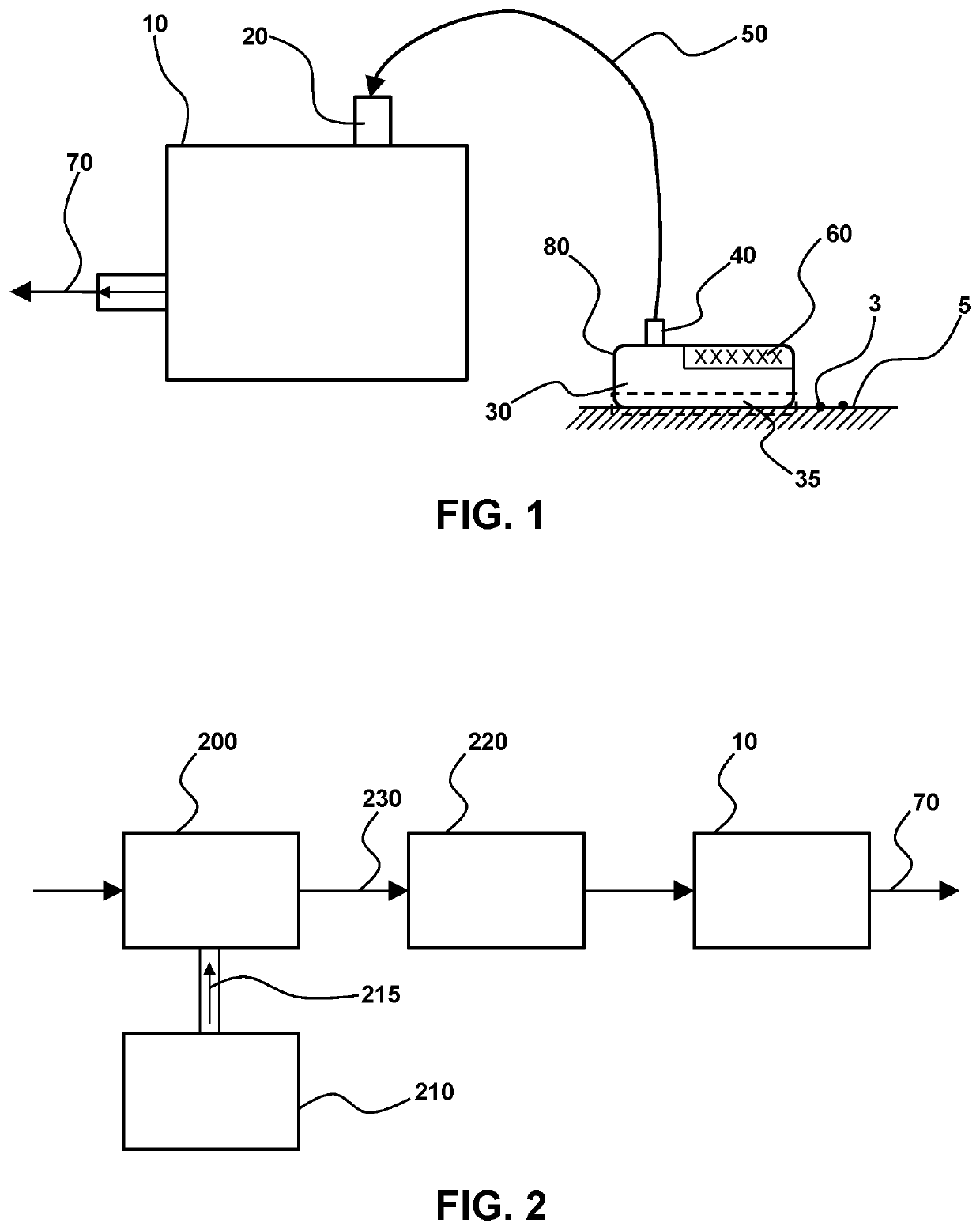
[0045]This example demonstrates a condensation particle counter with an attached ejection and sampling device (e.g. a sample puck or wand).

[0046]Described herein are systems and methods for monitoring of particles adhering to surfaces by adapting a condensation particle counter with a sample puck. The device generates a metered flow of filtered clean air and delivers it to the sample puck for dislodging particles from a surface. The resultant air stream with dislodged particles is then pulled from the sample puck into the condensation particle counter with a vacuum system. The vacuum system may utilize a matching flow rate to the dislodging flow rate. As particle size reduces, electrostatic and stiction characteristics make the particles progressively harder to eject from the surface for potential collection and counting. More aggressive particle removal techniques may be used to effectively remove them from surfaces. Some example removal techniques include: Metered air flow; Therma...


PUM

PropertyMeasurementUnit
effective diameteraaaaaaaaaa
total massaaaaaaaaaa
diameteraaaaaaaaaa

Abstract

Provided herein is a particle analyzer that is operably connected to a probe unit that is capable of both dislodging particles from a surface and sampling the particles after they have been dislodged. The devices and methods described herein may be lightweight and / or handheld, for example, so that they may be used within a cleanroom environment to clean and sample permanent surfaces and tools. The devices may include optical particle counters that use scattered, obscured or emitted light to detect particles, including condensation particle counting systems or split detection optical particle counters to increase the sensitivity of the device and thereby facilitate detection of smaller particles, while avoiding the increased complexity typically required for the detection of nanoscale particles, such as particles less than 100 nm in effective diameter.

Description

CROSS REFERENCE TO RELATED APPLICATIONS[0001]This application claims the benefit of priority to U.S. Provisional Patent Application No. 62 / 726,851 filed Sep. 4, 2018, which is incorporated herein by reference in its entirety to the extent not inconsistent herewith.BACKGROUND OF THE INVENTION[0002]Advancement of the various technologies requiring cleanroom manufacturing has led to a desire for the detection of smaller and smaller particles. Both microelectronic foundries and pharmaceutical / biological cleanrooms are beginning to seek detection of particles less than 20 nm in size as they may affect the increasingly sensitive manufacturing processes.[0003]Smaller particles, specifically particles less than 100 nm, can pose additional difficulties for maintaining a cleanroom environment because they are much more likely to interact or adhere to a surface within the cleanroom environment due to electrostatic, physical, chemical or magnetic forces between the particle and the surface. At ...

Claims


Application Information

Patent Timeline
Patent Type & Authority Patents(United States)
IPC IPC(8): G01N15/06G01N21/05B82Y35/00G01N15/00
CPCG01N15/065G01N21/05B82Y35/00G01N2015/0038G01N1/02G01N2001/028G01N2001/002G01N15/14
Inventor KNOLLENBERG, BRIAN A.RODIER, DANIEL ROBERT
Owner PARTICLE MEASURING SYST
Why Eureka
Try Eureka