
Lighting module

a technology of lighting modules and modules, applied in the field of lighting modules, to achieve the effects of improving the efficiency of luminaires, improving thermal energy dissipation, and facilitating positioning of lighting modules

Active Publication Date: 2021-02-23
SIGNIFY HLDG BV
View PDF19 Cites 0 Cited by
  • Summary
  • Abstract
  • Description
  • Claims
  • Application Information

AI Technical Summary

Benefits of technology

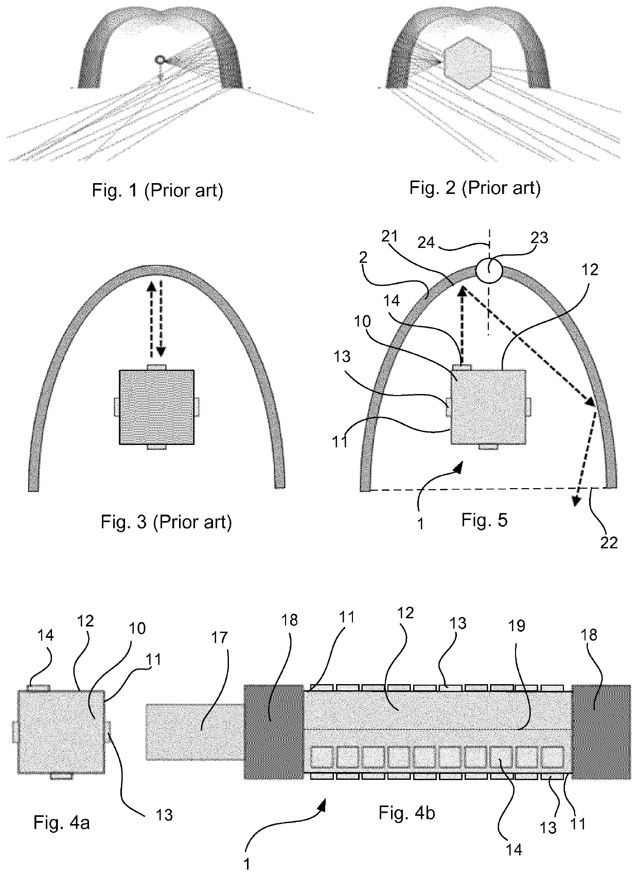
[0014]The above mentioned problems relating to the heat sink shadowing the light emitted by the lighting module and reflected by a reflector of a luminaire are particularly troublesome for light emitted from a point of origin and in a direction where the light will hit the surface of the reflector, in which the lamp is mounted, orthogonally or substantially orthogonally on the surface of the reflector, as this light will mainly be reflected back in the direction from where it originated, thus being reflected back towards the heat sink. The lighting module of the invention may reduce the amount of light reflected back towards the heat sink as the accumulated light emitting area of the first surface may, at least in part, be distributed apart or shifted from the centre line of the first surface. Light emitted from this area may therefore, when the lighting module is mounted in a luminaire, to a larger degree be emitted in a direction which is not radially outwards from an optical center of the reflector.
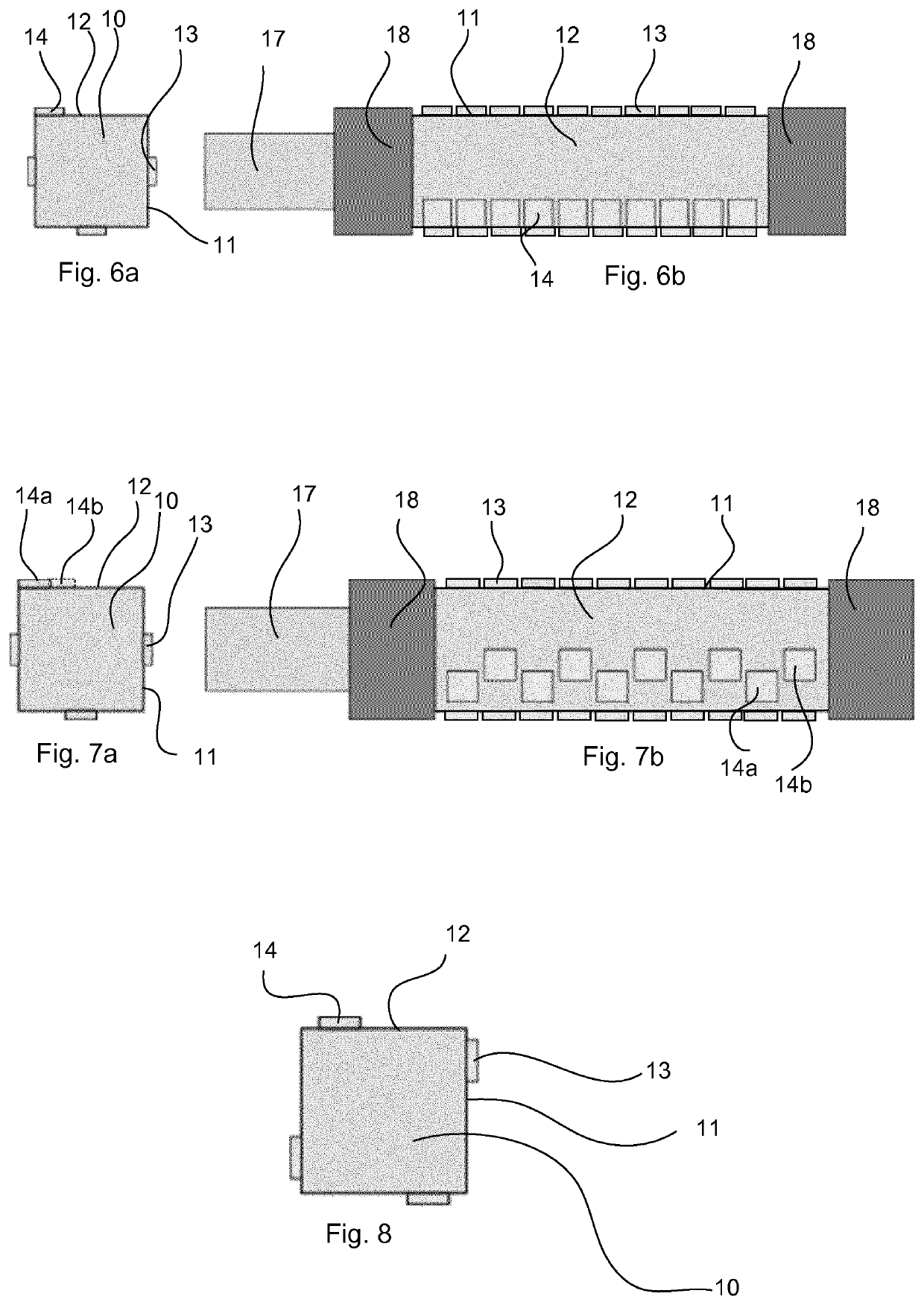
[0055]In an embodiment of the invention, the lighting module comprises a heat pipe to improve dissipation of thermal energy and / or to improve thermal management. More specifically, the heat pipe may improve dissipation of heat energy from one or more LEDs of the lamp. This may be achieved by including a heat pipe working as a heat transfer device and potentially combining the principles of thermal conductivity and phase transition to improve heat dissipation of thermal energy and thermal management. The heat pipe may be a constant conductance heat pipe, a vapor chamber, a variable conductance heat pipe, a pressure controlled heat pipe, a diode heat pipe, a thermosiphon, rotating heat pipe, or any other heat pipe type.

Problems solved by technology

The above mentioned problems relating to the heat sink shadowing the light emitted by the lighting module and reflected by a reflector of a luminaire are particularly troublesome for light emitted from a point of origin and in a direction where the light will hit the surface of the reflector, in which the lamp is mounted, orthogonally or substantially orthogonally on the surface of the reflector, as this light will mainly be reflected back in the direction from where it originated, thus being reflected back towards the heat sink.

Method used


Image

  • Lighting module
  • Lighting module
  • Lighting module

Examples


Embodiment Construction

[0083]The present invention will now be described more fully hereinafter with reference to the accompanying drawings, in which currently preferred embodiments of the invention are shown. This invention may, however, be embodied in many different forms and should not be construed as limited to the embodiments set forth herein; rather, these embodiments are provided for thoroughness and completeness, and to fully convey the scope of the invention to the skilled person.

[0084]Turning first to FIG. 1, a ray tracing simulation of a High Pressure Sodium (HPS) lamp of the prior art mounted in a reflector of a luminaire is shown. The HPS lamp generates light by an electric arc, thereby emitting light omnidirectionally, both downwards towards a light window, i.e. the opening of the reflector and towards the reflective surface of the reflector. The ray tracing simulation is based on a reflector of a typical street lamp which have a cross-sectional shape adapted to reflect light downwards towar...


PUM


Abstract

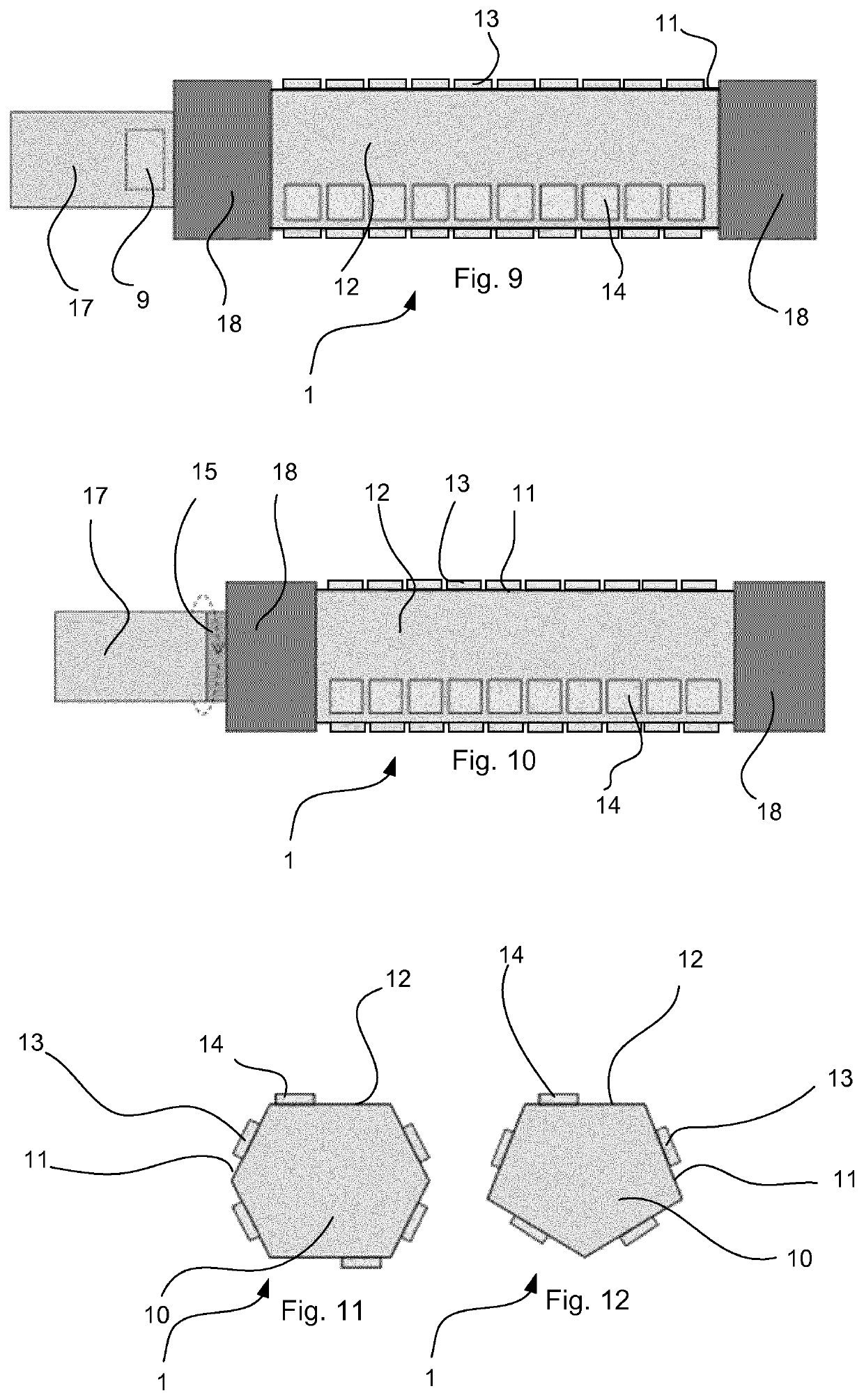
A lighting module (1) for use in a luminaire, comprising a heat sink (10) for dissipating thermal energy, which heat sink (10) is polygonal in cross section, forming a number of surfaces (11, 12) corresponding to the polygonal shape of the heat sink (10), each surface (11, 12) extending in a longitudinal direction, said longitudinal direction extending substantially perpendicularly to a plane of said cross section, each surface (11, 12) having a centre line (19) extending in said longitudinal direction, at least two LEDs (13, 14) being located on each of at least three of said surfaces (11, 12), wherein all of the LEDs (14) on a first (12) of said at least three surfaces (11, 12) defines an accumulated light emitting area of said first surface (12), which accumulated light emitting area is distributed asymmetrically in relation to the centre line (19) of said first surface (12).

Description

CROSS-REFERENCE TO PRIOR APPLICATIONS[0001]This application is the U.S. National Phase application under 35 U.S.C. § 371 of International Application No. PCT / EP2018 / 068660, filed on Jul. 10, 2018, which claims the benefit of European Patent Application No. 17182276.0, filed on Jul. 20, 2017. These applications are hereby incorporated by reference herein.FIELD OF THE INVENTION[0002]The invention relates to a lighting module for replacing gas-discharge arc lamps of an existing gas-discharge lamp luminaire, a luminaire comprising such a lighting module, and a method for replacing a gas-discharge lamp with such a lighting module.BACKGROUND OF THE INVENTION[0003]Gas-discharge lamps, especially High Pressure Sodium (HPS) arc lamps, are widely used for road and residential lighting, decorative floodlighting, commercial and industrial applications, and recreational sports facilities that are both indoor and outdoor. Such lamps comprise a bright arc which emits light in an omnidirectional wa...

Claims


Application Information

Patent Timeline
Patent Type & Authority Patents(United States)
IPC IPC(8): F21K9/65F21V29/70H05B45/10F21V7/00F21K9/237F21K9/68F21Y115/10
CPCF21K9/65F21K9/237F21K9/68F21V7/0008F21V29/70H05B45/10F21Y2115/10F21K9/23F21V29/503F21W2131/103F21W2131/10F21Y2107/30
Inventor KUPPENS, SIMON JACOBUS MARIAWONDERGEM-DE BEST, ANNA WILHEKMINA MARIAVAN BOMMEL, TIESVAN EEUWIJK, ALEXANDER HENRICUS WALTHERUSMARTIN, GENEVIEVE
Owner SIGNIFY HLDG BV
Learn More