
Releasable cable tie

a releasable, cable technology, applied in the direction of electrical equipment, flexible elements, packaging, etc., can solve the problems of inconvenient and costly, damage to electrical power cords or electrical cables, and the inability to release without damage to electrical power cords, so as to increase the resistance of the releasable tie against pulling, reduce the entry resistance of the strap, and facilitate the insertion of the strap body

Active Publication Date: 2021-02-23
KML HLDG GRP LLC
View PDF20 Cites 0 Cited by
  • Summary
  • Abstract
  • Description
  • Claims
  • Application Information

AI Technical Summary

Benefits of technology

The present invention provides a releasable tie that reduces resistance for easy insertion of a strap into a locking head. The tie has a small gap between the engaging teeth of the locking head and the strap, making it easier to insert. The tie also has predetermined depth between the operating rod and the engaging tooth of the locking head to increase resistance against pulling. Additionally, the tie features an extension length for the operating rod to prevent overturning and a user-friendly design for easy disengagement of the locking teeth. The releasable tie is easy to use, cost-effective, and safe for use without causing damage to electrical power cords or cables.

Problems solved by technology

Commercially available ties today, when tightened, cannot be released without damage to electrical power cords or electrical cables when bundled and tied tightly.
When it is desired to add or remove more electrical power cords or electrical cables or objects in a tied bundle or to rearrange the objects already tied up, conventional ties must be cut and be replaced by new ones, which is not only inconvenient and costly, but more importantly, it leads to damage to the electrical power cords or electrical cables.
Whenever any electrical power cord or electrical cable in a bundled tie is damaged, the entire electrical wiring must be replaced and redone.

Method used


Image

  • Releasable cable tie
  • Releasable cable tie
  • Releasable cable tie

Examples


Embodiment Construction

[0035]The present invention provides novel apparatus and method including a releasable cable tie wherein the engaging teeth of an elongated strap are employed and operated in novel manner of releasable engagement between the engaging teeth of a locking head for achieving a fixing effect. The drawings referred to in the following detailed description identify, describe, and demonstrate the important features of the novel releasable cable tie of the present invention.

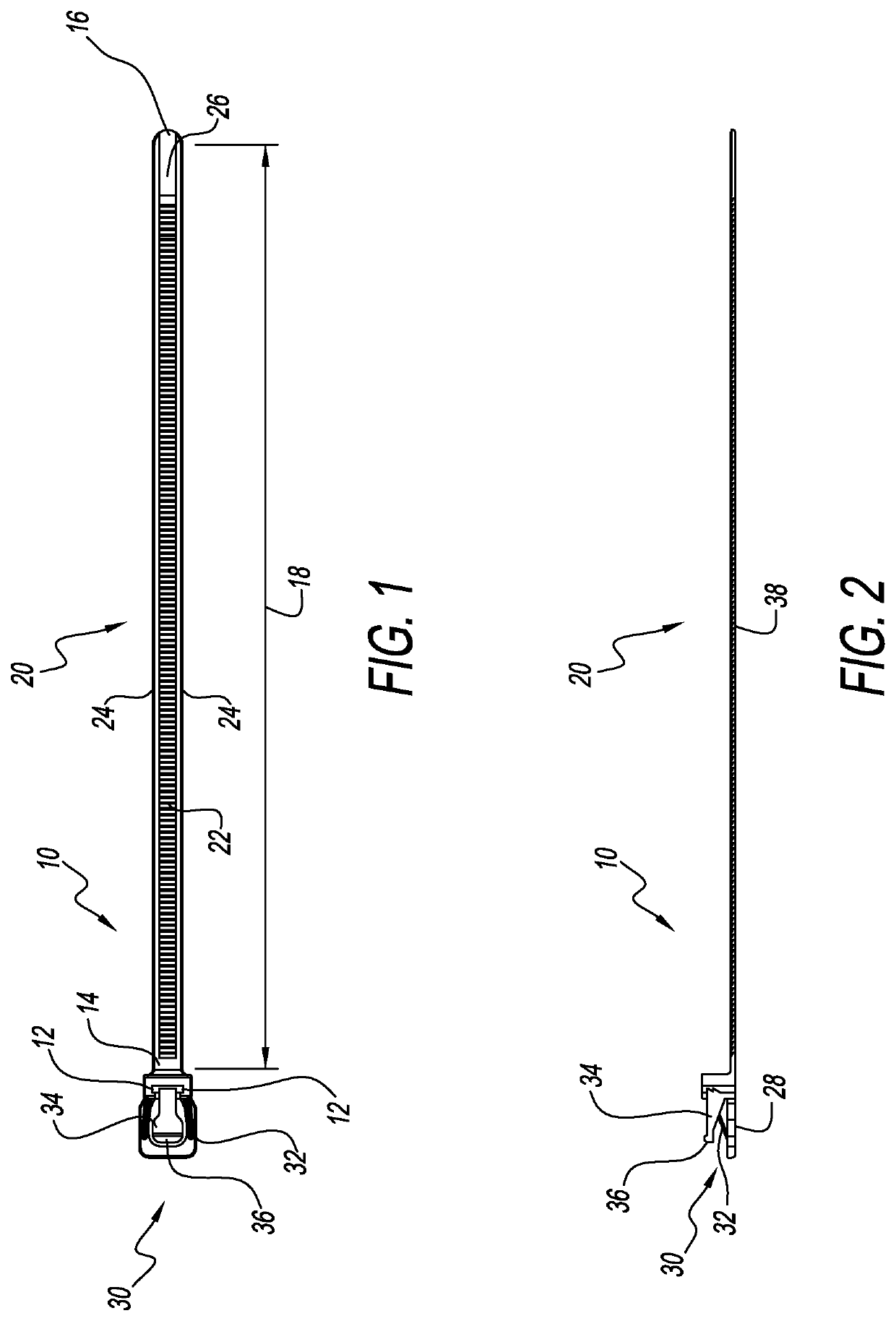
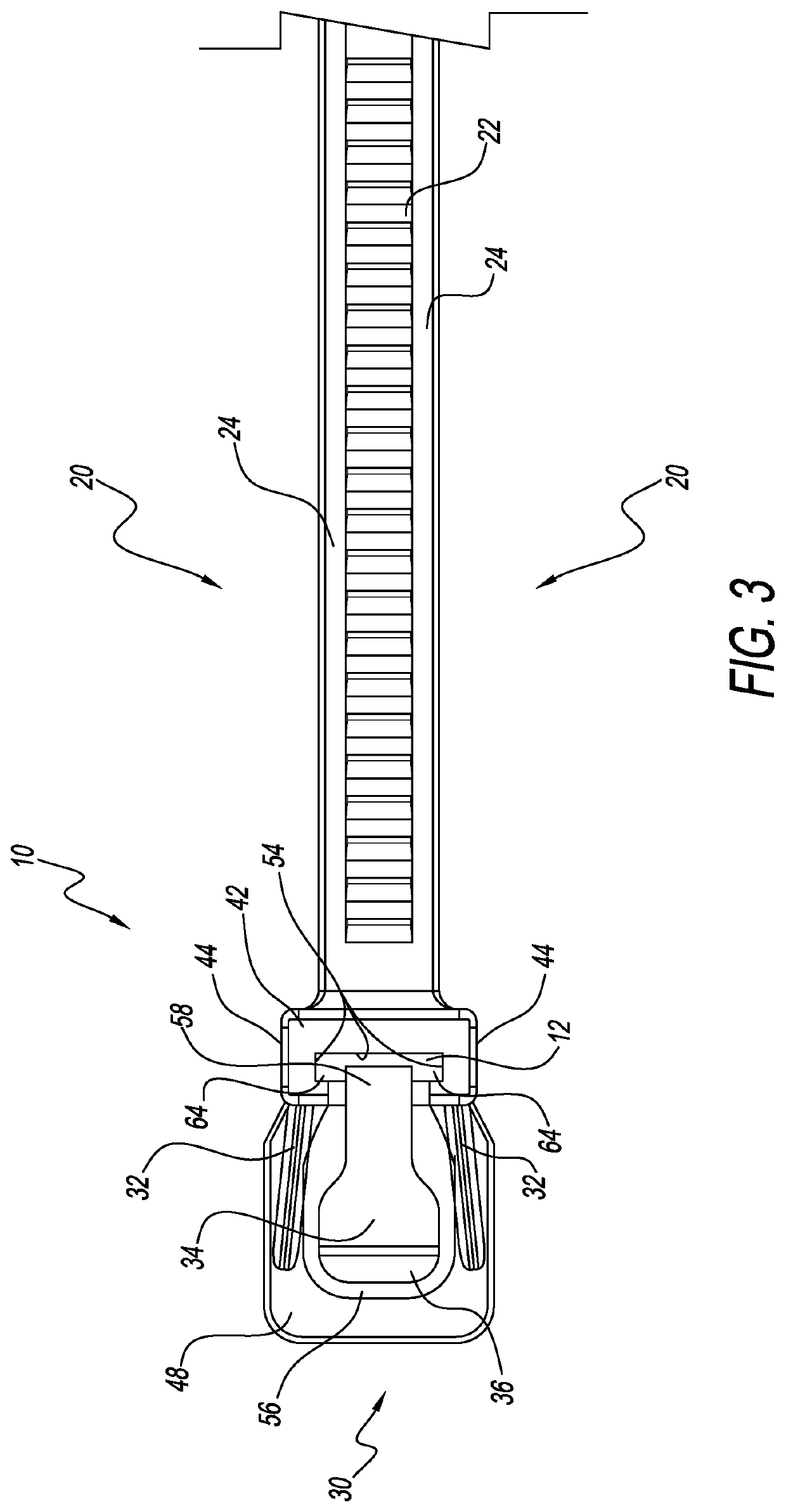
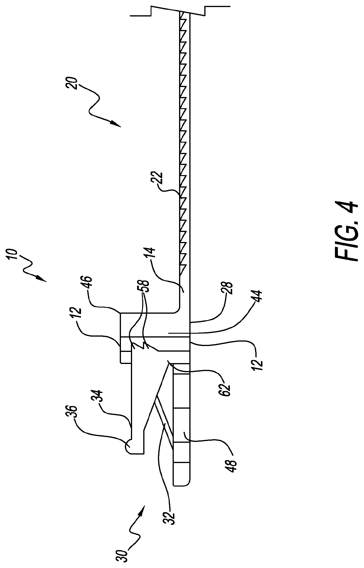
[0036]Referring now to FIG. 1, a releasable tie 10 according to a preferred embodiment of the present invention includes an elongated planar strap 20 and a locking head 30. The locking head 30 is formed to have a window 12, wherein the window 12 provides a channel, passageway, or window extending entirely through the locking head 30. The elongated strap 20 has a first end 14 and a second opposite end 16. The first end 14 of strap 20 is connected to the looking head 30. The second opposite end 16 of strap 20 can be inserte...


PUM

PropertyMeasurementUnit
widthaaaaaaaaaa
widthaaaaaaaaaa
widthaaaaaaaaaa

Abstract

A releasable cable tie and method providing a molded one-piece thermoplastic elongated planar strap for binding electrical cables and a plurality of strap teeth formed on one side of the strap for engaging a locking head formed at one end of the strap. A novel releasable latch on the locking head provides a large and wide thumb pad having a width at least 95% of the width of the strap and an index finger back plate positioned below the thumb pad and having a width and length at least as large as the width and height of the thumb pad.

Description

[0001]This application is a continuation-in-part of prior U.S. Provisional Patent Application Ser. No. 62 / 593,908, filed Dec. 2, 2017.BACKGROUND OF THE INVENTION1. Technical Field[0002]The present invention relates to tie apparatus and method for tying and holding objects together. In one aspect, the present invention relates to tie apparatus and method for tying together electrical cables. In one aspect, the present invention relates to an electrical cable tie apparatus and method for use in the aviation industry.2. Description of Related Art[0003]Ties are used to tie and fasten electrical power cords or electrical cables or other objects to be bundled, for the purpose of holding the electrical power cords or electrical cables bundled neatly and securely together.INTRODUCTION TO THE INVENTION[0004]U.S. Pat. No. 8,499,419 discloses a releasable tie having arm 17 to facilitate disengagement but nowhere discloses the size dimensions of arm 17.[0005]U.S. Pat. No. 4,236,280 discloses a ...

Claims


Application Information

Patent Timeline
Patent Type & Authority Patents(United States)
IPC IPC(8): B65D63/10H02G3/32
CPCB65D63/1072H02G3/32B65D2563/106B65D2563/107
Inventor MCDOWELL, III, GEORGE R.
Owner KML HLDG GRP LLC
Learn More