Electromagnetic wave detecting apparatus and method of setting acquisition timing of detection signal
a technology of electromagnetic wave and detection signal, applied in the field of electromagnetic wave detecting apparatus, can solve the problem of relatively complicated circuit configuration, and achieve the effect of preventing a complicated circuit configuration
- Summary
- Abstract
- Description
- Claims
- Application Information
AI Technical Summary
Benefits of technology
Problems solved by technology
Method used
Image
Examples
first practical example
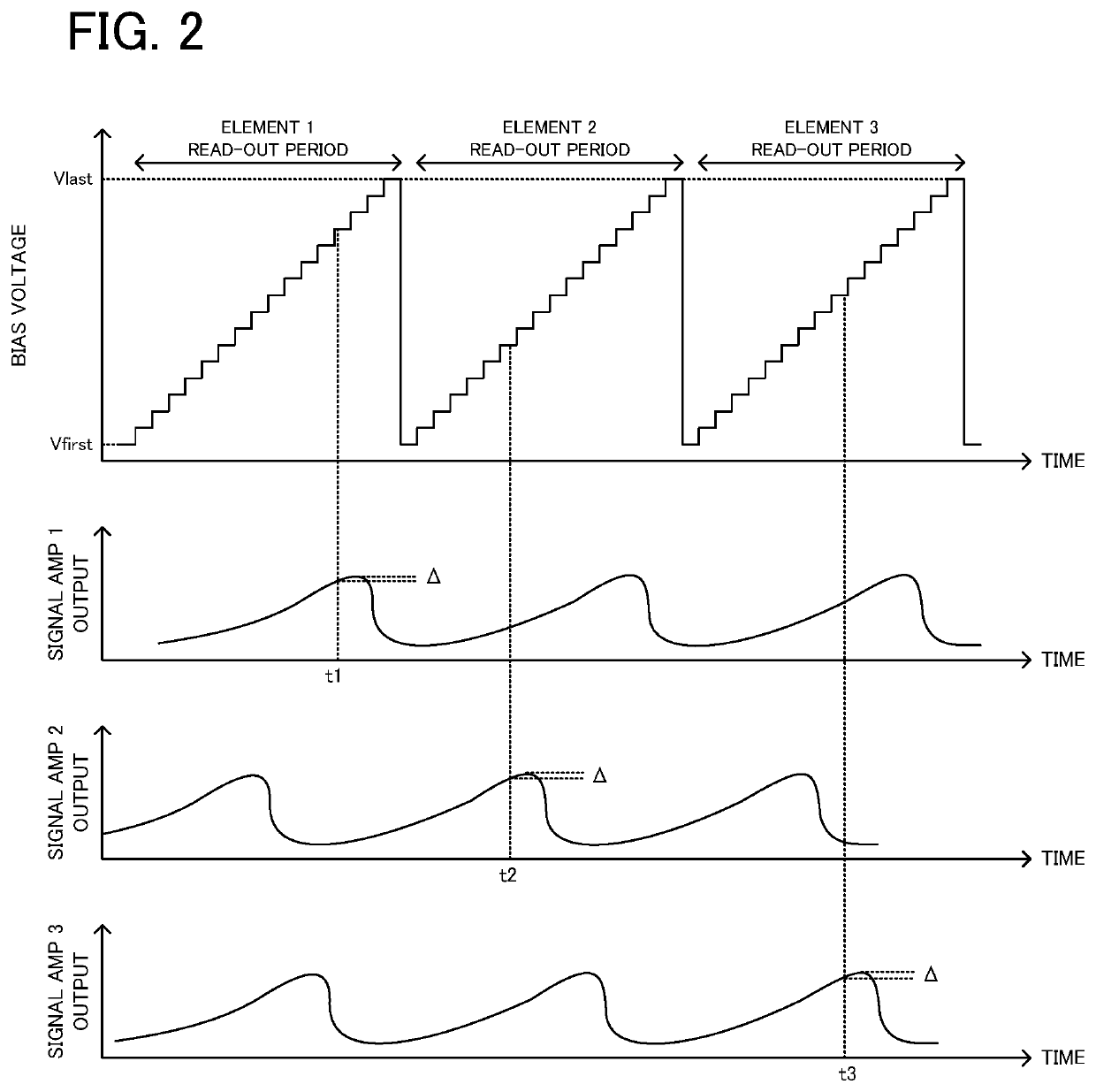
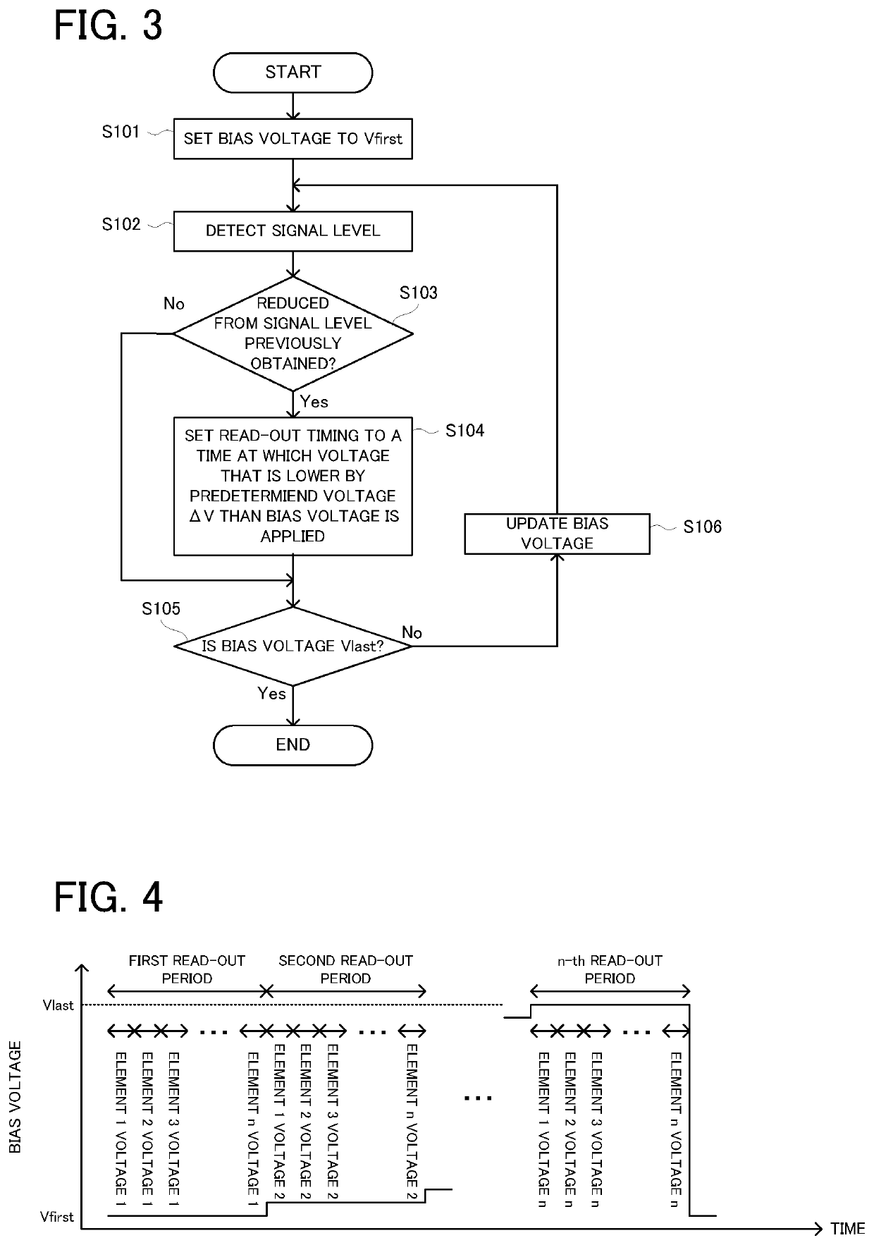
[0028]A terahertz wave detecting apparatus according to a first practical example, which is an example of the electromagnetic wave detecting apparatus according to the present invention, will be explained with reference to FIG. 1 to FIG. 3.
(Configuration of Apparatus)
[0029]A configuration of the terahertz wave detecting apparatus according to the first practical example will be explained with reference to FIG. 1. FIG. 1 is a block diagram illustrating the configuration of the terahertz wave detecting apparatus according to the first practical example.
[0030]In FIG. 1, a terahertz wave detecting apparatus 100 is provided with: a plurality of terahertz wave detecting elements 1, 2, 3, . . . , n; a plurality of bias tee circuits 1, 2, 3, . . . , n, which are respectively electrically connected to the terahertz wave detecting elements 1, 2, 3, . . . , n; a bias voltage generator 11 configured to apply bias voltage to each of the terahertz wave detecting elements 1, 2, 3, . . . , n, via r...
modified example
[0051]In the aforementioned first practical example, as illustrated in FIG. 2, the terahertz wave detecting element that is a sampling target is changed in every period of the sawtooth wave of the bias voltage. For example, as illustrated in FIG. 4, every time the voltage value of the bias voltage is changed, all the terahertz wave detecting elements 1, 2, 3, . . . , n may be set as sampling targets, and the detection signal from the terahertz wave detecting element whose current bias voltage is the optimum bias voltage may be actually sampled.
[0052]Moreover, in the aforementioned first practical example, the voltage that is lower by the predetermined voltage than the bias voltage that allows the maximum detection sensitivity of each terahertz wave detecting element is set as the “optimum bias voltage”. The bias voltage that allows the maximum detection sensitivity of each terahertz wave detecting element may be also set as the “optimum bias voltage”.
[0053]Moreover, the bias voltage...
second practical example
[0054]A terahertz wave detecting apparatus according to a second practical example, which is an example of the electromagnetic wave detecting apparatus according to the present invention, will be explained with reference to FIG. 5 and FIG. 6. The second practical example is the same as the aforementioned first practical example, except that the circuit configuration is partially different. Thus, in the second practical example, the same explanation as that in the first practical example will be omitted, as occasion demands, and the same parts on the drawings will carry the same reference numerals. An explanation will be given only to basically different points with reference to FIG. 5 and FIG. 6.
(Configuration of Apparatus)
[0055]A configuration of the terahertz wave detecting apparatus according to the second practical example will be explained with reference to FIG. 5. FIG. 5 is a block diagram illustrating the configuration of the terahertz wave detecting apparatus according to th...
PUM
 Abstract
Description
Claims
Application Information
 - R&D
- Intellectual Property
- Life Sciences
- Materials
- Tech Scout
- Unparalleled Data Quality
- Higher Quality Content
- 60% Fewer Hallucinations
Browse by: Latest US Patents, China's latest patents, Technical Efficacy Thesaurus, Application Domain, Technology Topic, Popular Technical Reports.
© 2025 PatSnap. All rights reserved.Legal|Privacy policy|Modern Slavery Act Transparency Statement|Sitemap|About US| Contact US: help@patsnap.com


