
Mechanical disc brake structure

a technology of mechanical disc brakes and mechanical discs, applied in the direction of braking systems, cycle equipments, cycle brakes, etc., can solve the problems of troublesome assembly of conventional reducing service life and use safety, and failing to meet today's needs for brake braking performance, etc., to prolong the service life enhance the safety of mechanical disc brake structures, and operate mechanical disc brake structures smoothly

Active Publication Date: 2021-02-09
HUANG I CHENG
View PDF8 Cites 0 Cited by
  • Summary
  • Abstract
  • Description
  • Claims
  • Application Information

AI Technical Summary

Benefits of technology

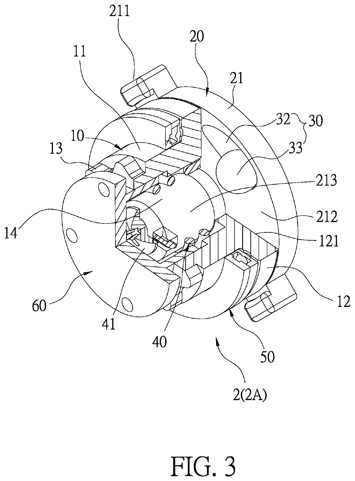
The present invention provides a disc brake structure that has a torsion spring placed in a rotation member's through aperture to prevent dust and objects from getting on the spring and causing it to corrode. This results in the brakes operating smoothly, lasting longer, and being safer. The torsion spring is connected to an engagement member through a brake line pull, making the mechanical disc brake structure easier to connect.

Problems solved by technology

Bicycles or sports equipment are traditionally using clip-on brakes, and their brake braking performance has failed to meet today's needs gradually.
However, the torsion spring of the conventional mechanical disc brake structure exposes outside, so dusts and foreign matters deposit on the torsion spring, and the torsion spring causes corrosion after a period of using time, thus reducing service life and using safety.
The torsion spring is disposed on the side of the body and is turned continuously after rotating the drive assembly, thereafter the torsion spring is locked, thus having troublesome assembly of the conventional mechanical disc brake structure.

Method used


Image

  • Mechanical disc brake structure
  • Mechanical disc brake structure
  • Mechanical disc brake structure

Examples


Embodiment Construction

[0024]The present invention will be clearer from the following description when viewed together with the accompanying drawings, which show, for purpose of illustrations only, a preferred embodiment in accordance with the present invention.

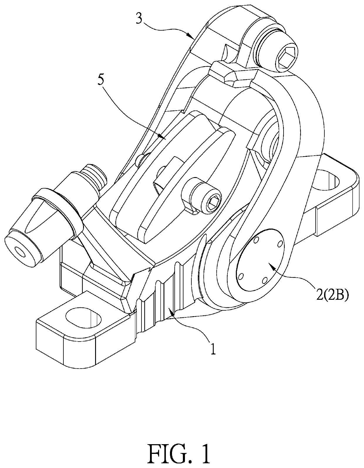
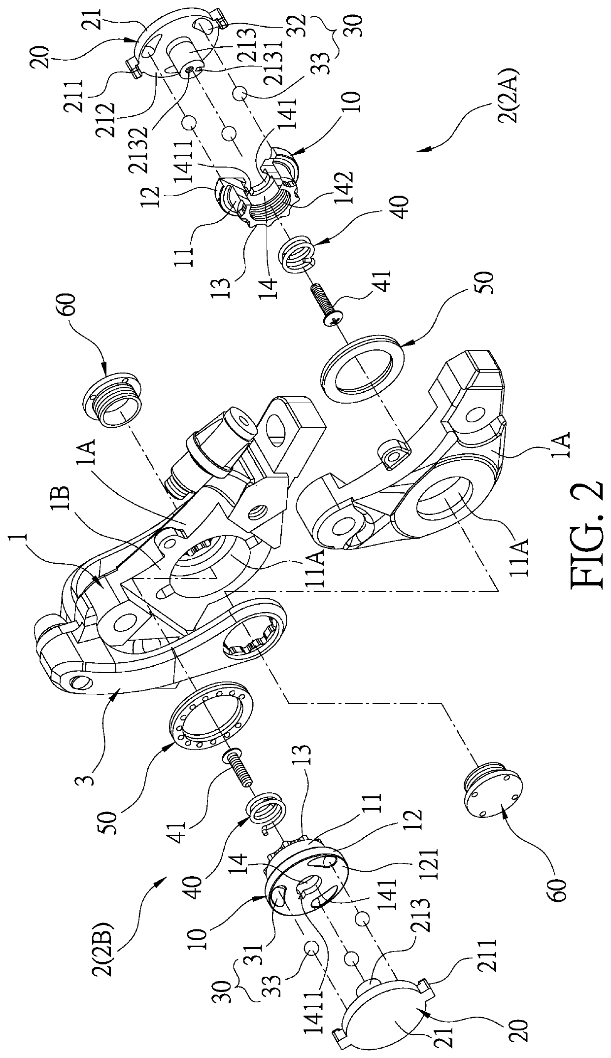
[0025]With reference to FIGS. 1-4, a mechanical disc brake structure according to a preferred embodiment of the present invention comprises: a body 1, at least one brake set 2, and a drive unit 3 (in this embodiment, the at least one brake set 2 includes a first brake set 2A and a second brake set 2B).

[0026]The body 1 includes two clamp seats 1A between which an accommodation space 1B is defined so as to accommodate a circular disc 4. The two clamp seats 1A have two receiving orifices 11A respectively, and the first brake set 2A is symmetrical to the second brake set 2B and is accommodated in the two receiving orifices 11A of the two clamp seats 1A.

[0027]The drive unit 3 is rotatably connected on the body 1 so as to synchronously drive the first br...


PUM


Abstract

A mechanical disc brake structure contains: a body, a brake set, and a drive unit. The body includes two clamp seats between which an accommodation space is defined so as to accommodate a circular disc. The brake set contains: a rotation member includes a coupling column, a rotatable block, and a connection portion. The rotatable block has a push face, the rotation member includes a through aperture, and the stop fringe has a first retaining portion. The engagement member includes a braking disc having a forced face and a shaft. The shaft has a second retaining portion and a threaded orifice. An actuation structure is defined between the push face and the forced face. A torsion spring is accommodated in the through aperture. A screw element is screwed with the threaded orifice, and a locking member is locked with the rotation member.

Description

BACKGROUND OF THE INVENTIONField of the Invention[0001]The present invention relates to a disc brake structure, and more particularly to a mechanical disc brake structure.Description of the Prior Art[0002]Bicycles or sports equipment are traditionally using clip-on brakes, and their brake braking performance has failed to meet today's needs gradually. In order to improve the braking performance and safety of bicycles or sports equipment, more and more brake systems for bicycles or sports equipment use disc brakes. The current disc brakes are distinguished into two systems (i.e., mechanical and hydraulic systems) depending on the driving method. The mechanical disc brake relies on the tension of the brake wire to rub the brake pads in the caliper and clamp the disc to produce a braking effect. The hydraulic disc brake pulls the brake to actuate the piston inside the piston to compress the oil, and the pressure passes through the caliper from the oil pipe, thus pushing the piston in t...

Claims


Application Information

Patent Timeline
Patent Type & Authority Patents(United States)
IPC IPC(8): F16D65/18F16D55/26B62L3/02F16D55/226F16D125/26F16D55/00
CPCF16D65/183F16D55/226B62L3/02F16D2055/0029F16D2125/26B62L1/005F16D55/2245F16D65/18F16D2121/14F16D2125/582B60T11/046F16D55/228F16D2125/36F16D2125/60F16D2125/64
Inventor HUANG, I-CHENG
Owner HUANG I CHENG
Learn More