Device for manufacturing particulate-containing article and method for manufacturing particulate-containing article
a technology for powder-containing articles and devices, which is applied in the direction of other domestic articles, synthetic resin layered products, bandages, etc., can solve the problems of unstable position of powder particles within the storage chamber, insufficient function of powder, user discomfort, etc., and achieve the effect of stable disposal
- Summary
- Abstract
- Description
- Claims
- Application Information
AI Technical Summary
Benefits of technology
Problems solved by technology
Method used
Image

Examples
first embodiment
(1) First Embodiment
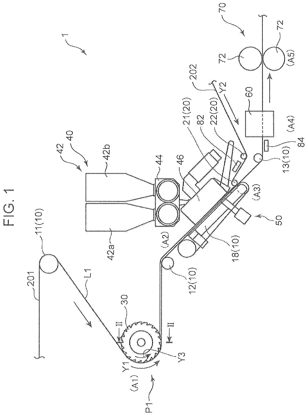
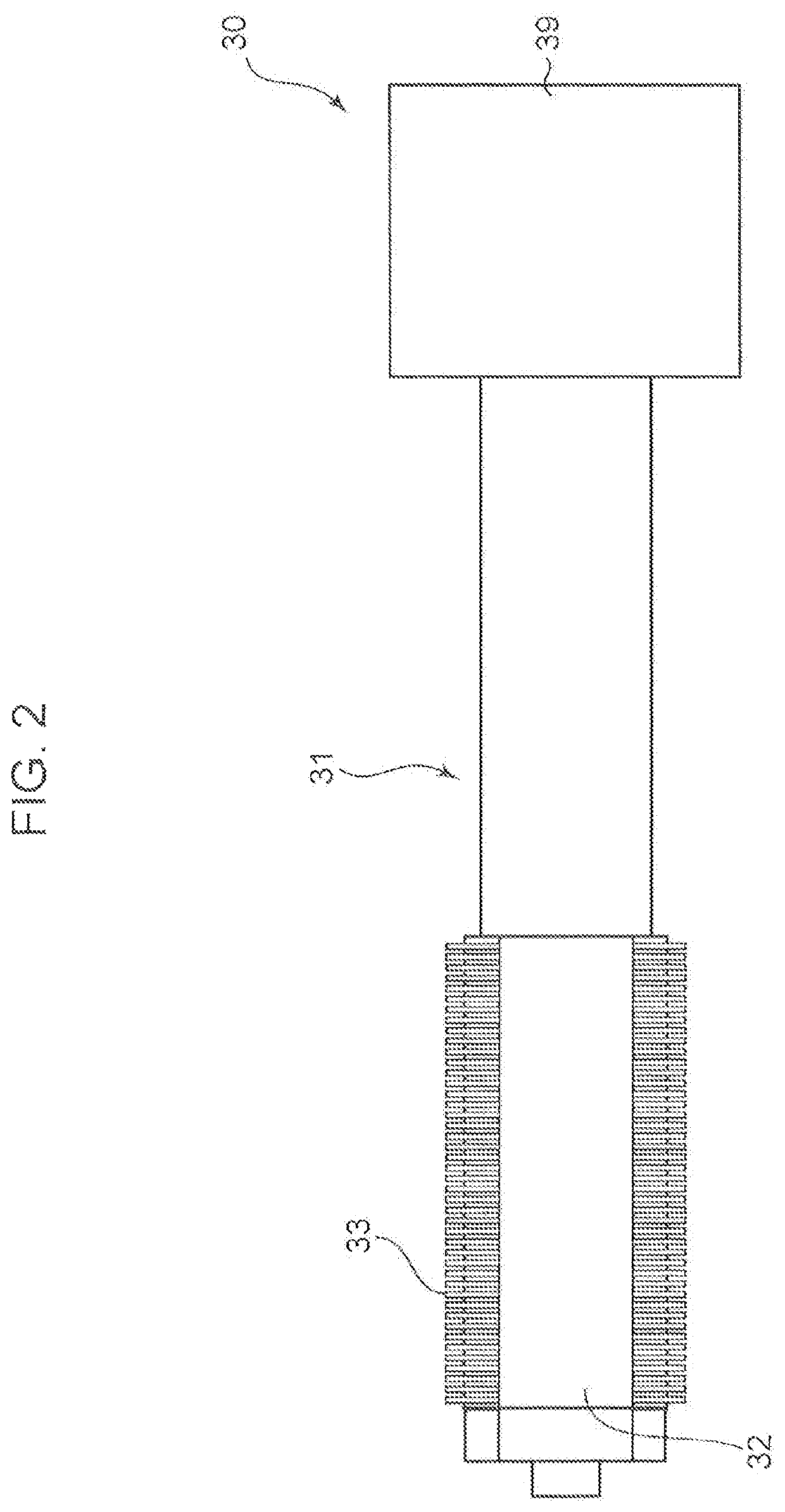
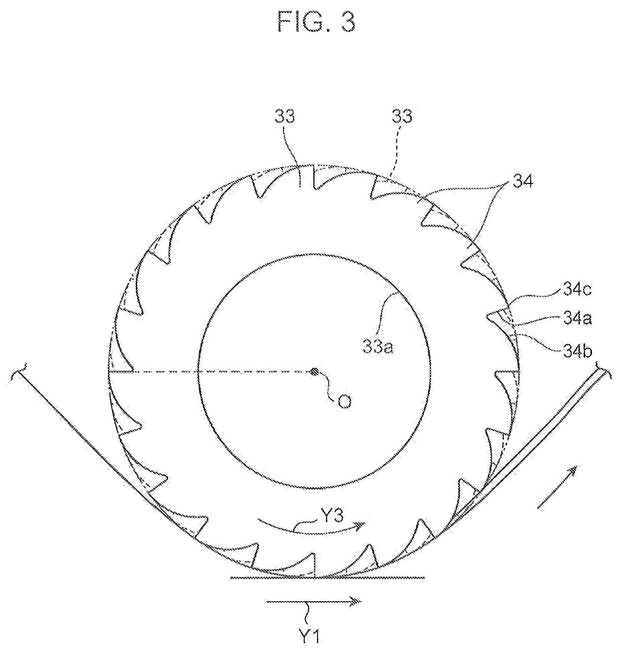
[0025]FIG. 1 is a schematic diagram depicting a powder-containing article manufacturing apparatus 1 according to a first embodiment of the present invention (hereinafter referred to simply as “manufacturing apparatus 1”). As depicted in FIG. 1, this manufacturing apparatus 1 comprises a first sheet conveyance device (sheet conveyance device) 10, a second sheet conveyance device 20, a fiber-raising device 30, a powder supply device 40, a suction device 50, a folding device 60, a pressure joining device 70, a first adhesive application device 82, and a second adhesive application device 84.
[0026]The manufacturing apparatus 1 is an apparatus for manufacturing a powder-containing article 2 containing a powder S. This embodiment will be described based on an example in which an article containing a liquid-absorbable powder S is manufactured as the powder-containing article. For example, this powder-containing article containing the liquid absorbable powder S is utiliz...
second embodiment
(2) Second Embodiment
[0119]Although the first embodiment has been described based on an example in which the belt conveyer 18 is used as a device for conveying the first sheet 201 to the powder distribution unit 46, a conveyance drum 518 may be used, in place of the belt conveyer 18, as depicted in FIG. 6. In this case, the first sheet 201 after being subjected to fiber-raising is supplied to an outer peripheral surface of the conveyance drum 518. Further, the powder S is supplied to the first sheet 201 at a position along the outer peripheral surface of the conveyance drum 518, and then, through the guide roll 21, the second sheet 202 is supplied to the first sheet 201 at a position along the outer peripheral surface of the conveyance drum 518. Then, between the guide roll 21 and the conveyance drum 518, the first sheet 201 and the second sheet 202 to which an adhesive is applied by the first adhesive application device 82 are bonded together while being pressure joined in the thic...
third embodiment
(3) Third Embodiment
[0121]The first embodiment has been described based on an example in which the guide roll 21 of the second sheet conveyance device 20 for supplying the second sheet 202 to the obverse surface of the first sheet 201 is disposed downstream (in the conveyance direction Y1 of the first sheet 201) of the position opposed to the distribution port 48c, i.e., downstream (in the conveyance direction Y1 of the first sheet 201) of the powder supply position where the powder S is supplied to the first sheet 201. Alternatively, the guide roll 21 may be disposed as depicted in FIG. 7 and FIG. 8 in which a part of FIG. 7 is enlargedly depicted.
[0122]Specifically, in the third embodiment, as depicted in FIG. 8, one 121 of two guide rolls of a second sheet conveyance device 20 for supplying the second sheet 202 to the obverse surface of the first sheet 201 is disposed at the position opposed to the distribution port 48c, i.e., at the powder supply position where the powder S is s...
PUM
| Property | Measurement | Unit |
|---|---|---|
| average fiber length measurement method | aaaaa | aaaaa |
| average fiber length measurement method | aaaaa | aaaaa |
| average fiber length measurement method | aaaaa | aaaaa |
Abstract
Description
Claims
Application Information
 - R&D
- Intellectual Property
- Life Sciences
- Materials
- Tech Scout
- Unparalleled Data Quality
- Higher Quality Content
- 60% Fewer Hallucinations
Browse by: Latest US Patents, China's latest patents, Technical Efficacy Thesaurus, Application Domain, Technology Topic, Popular Technical Reports.
© 2025 PatSnap. All rights reserved.Legal|Privacy policy|Modern Slavery Act Transparency Statement|Sitemap|About US| Contact US: help@patsnap.com