Position detecting sensor, position detecting device, and information processing system

a technology of position detection and sensor, applied in the field of position detecting sensor, position detecting device, information processing system, can solve the problems of linearity degradation, inability to maintain linearity of the result of detection of the indicated position, etc., and achieve the effect of improving the linearity of detection accuracy

Active Publication Date: 2021-02-02
WACOM CO LTD
View PDF10 Cites 0 Cited by
  • Summary
  • Abstract
  • Description
  • Claims
  • Application Information

AI Technical Summary

Benefits of technology

[0009]In view of the above, in relation to position detecting sensors using metallic mesh electrodes, it is an object to more improve the linearity of accuracy of detection of a position indicated (coordinates indicated) by a stylus, and thereby enable minute indication input to be performed more properly (excellently).
[0012]That is, the first and second electrodes are formed such that a net is woven by using metallic thin wires, and are thus in a mesh form (reticulate form) in which a large number of meshes (interstices) are provided. Making the first electrodes different from the second electrodes in one or both of width in the arrangement direction and mesh density enables sufficient coupling capacitances to be secured between the electrodes located on a back side as viewed from an operating surface side with which the stylus (electronic pen) comes into contact and the stylus. Further, the characteristics of the coupling capacitances are made as flat as possible. It is thereby possible to improve detection accuracy of stylus detection (for indication input by the stylus).

Problems solved by technology

Thus, in a case where a sufficient coupling capacitance is not obtained, there is a possibility of a result of detection of an indicated position deviating from an actual indicated position.
That is, there is a possibility of a degradation in linearity of the result of detection of the indicated position.
However, when the width of the first electrodes is widened, the first electrodes obstruct the electrostatic coupling between the stylus and the second electrodes to a greater extent, and the linearity of the result of detection of the indicated position cannot be maintained.

Method used


Image

  • Position detecting sensor, position detecting device, and information processing system
  • Position detecting sensor, position detecting device, and information processing system
  • Position detecting sensor, position detecting device, and information processing system

Examples


first embodiment

[Outline of Transparent Sensor and Position Detecting Device]

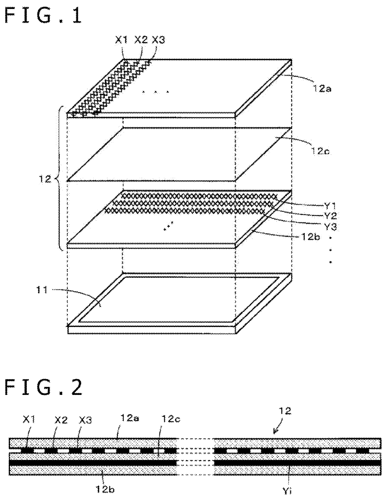
[0023]FIG. 1 is a diagram of assistance in explaining a position detecting sensor according to an embodiment of the present disclosure. As depicted in FIG. 1, a transparent sensor 12 having electrodes (mesh electrodes) formed in a mesh form by metallic thin wires is provided on an LCD panel 11. One embodiment of the position detecting sensor according to the present disclosure is applied to the transparent sensor 12. Incidentally, the metallic thin wires constituting the mesh electrodes are formed of copper, silver, or another metal having a low resistance value.

[0024]The transparent sensor 12 according to the present embodiment is configured as follows. As indicated by mesh electrodes Y1, Y2, Y3, . . . in FIG. 1, a Y-direction mesh electrode group made by arranging a plurality of mesh electrode lines in a Y-direction (longitudinal direction in FIG. 1) is formed on an insulating layer 12b. Similarly, as indicated by mesh e...

second embodiment

[Outline of Transparent Sensor and Position Detecting Device]

[0059]Description will next be made of a second embodiment of the transparent sensor and the position detecting device. In the case of the transparent sensor 12 according to the foregoing first embodiment, as described with reference to FIG. 5C, the coupling capacitance between the stylus and the Y-electrode slightly changes in the longitudinal direction of the Y-electrode. Accordingly, a transparent sensor according to the present second embodiment makes the characteristic of the coupling capacitance between the stylus and the Y-electrode flat with a smaller change, and thus can more improve the linearity of a result of detection of an indicated position.

[0060]A basic configuration of the transparent sensor 12A according to the present second embodiment is similar to that of the transparent sensor 12 according to the first embodiment described with reference to FIG. 1. The basic configuration of the transparent sensor 12A...

third embodiment

[Outline of Transparent Sensor and Position Detecting Device]

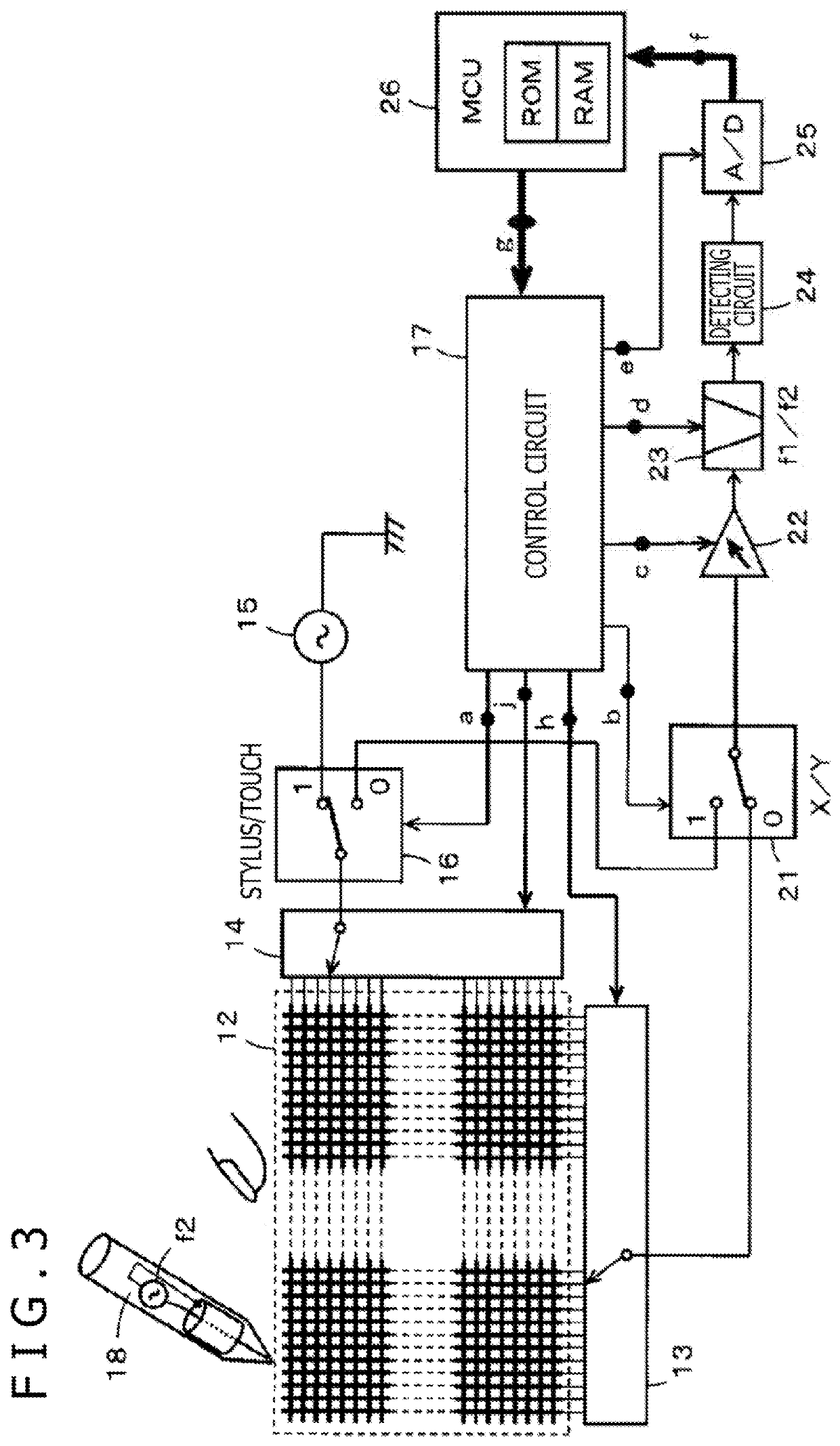
[0077]Description will next be made of a third embodiment of the transparent sensor and the position detecting device. A basic configuration of the transparent sensor 12B according to the present third embodiment is similar to that of the transparent sensor 12 according to the first embodiment described with reference to FIG. 1. The basic configuration of the transparent sensor 12B is constituted by an insulating layer 12aB on which X-electrodes are arranged in an X-direction (horizontal direction), an insulating layer 12c, and an insulating layer 12bB on which Y-electrodes are arranged in a Y-direction (vertical direction). In addition, the position detecting device according to the present third embodiment is configured in a similar manner to the position detecting device described with reference to FIG. 3. However, the position detecting device according to the present third embodiment is configured using the transparen...


PUM


Abstract

A position detecting sensor includes a plurality of first electrodes arranged in a first direction; and a plurality of second electrodes arranged in a second direction intersecting the first direction. The plurality of first electrodes and the plurality of second electrodes are formed in a mesh form. One or both of: (i) a width of each of the plurality of first electrodes in an arrangement direction of the plurality of first electrodes is different from a width of each of the plurality of second electrodes in an arrangement direction of the plurality of second electrodes, and (ii) a mesh density of each of the plurality of first electrodes is different from a mesh density of each of the plurality of second electrodes.

Description

BACKGROUNDTechnical Field[0001]The present disclosure relates to a position detecting sensor capable of receiving an indication input by a stylus (electronic pen), and a position detecting device and an information processing system that use the position detecting sensor.Background Art[0002]Various electronic apparatuses equipped with a touch panel have come into wide use. The touch panel is a device that is constituted of a display device such as a liquid crystal display (LCD) or the like and a touch sensor, and implements a display function and an input function. The touch sensor is to detect a position indicated by an indicator such as a finger of a user, a passive pen, or the like. The touch sensor is generally disposed on the display screen of the display device.[0003]Therefore, the touch sensor is formed as a transparent touch sensor so as not to render information displayed on the display screen of the display device difficult to see. Japanese Patent Laid-open No. 2010-086684...

Claims


Application Information

Patent Timeline
Patent Type & Authority Patents(United States)
IPC IPC(8): G06F3/0354G06F3/044G06F3/03G06F3/041
CPCG06F3/03545G06F3/0321G06F3/0416G06F3/0442G06F3/0445G06F3/0446G06F3/0448G06F2203/04112
Inventor MIURA, YOICHIHARA, HIDEYUKI
Owner WACOM CO LTD
Why Eureka
Try Eureka