
Display device and method of manufacturing the same

a technology of a display device and a manufacturing method, which is applied in the direction of instruments, mechanical devices, optical elements, etc., can solve the problems of low adhesive power, inability to effectively serve as a bonding agent having barrier characteristics, and inability to prevent moisture from penetrating from the outside, so as to achieve excellent design compatibility

Active Publication Date: 2021-01-26
SAMSUNG DISPLAY CO LTD
View PDF24 Cites 0 Cited by
  • Summary
  • Abstract
  • Description
  • Claims
  • Application Information

AI Technical Summary

Benefits of technology

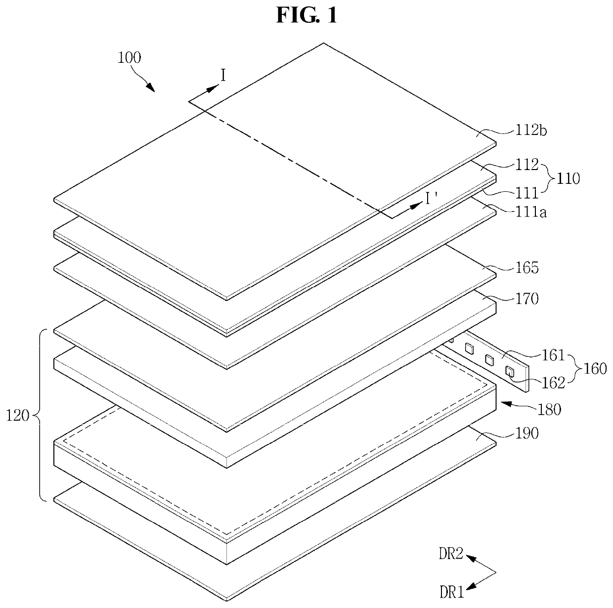
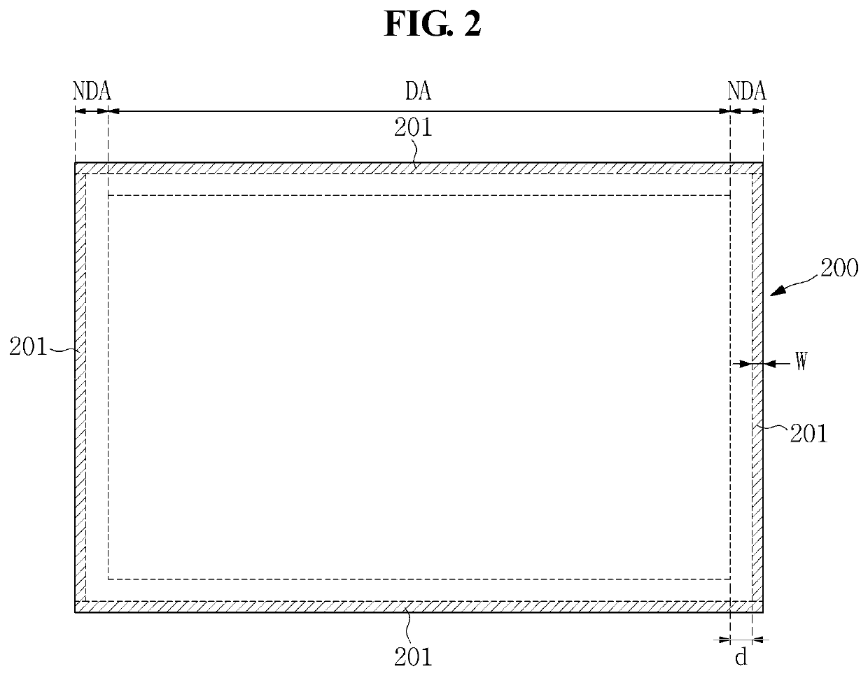
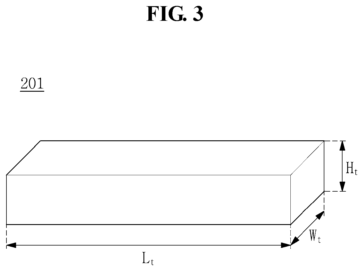
[0013]The present disclosure is directed to a display device which is capable of implementing a narrow bezel through the attachment of a display panel and a glass light guide plate by melting a spacer having a uniform width along a thickness direction by means of laser beams and is also capable of providing excellent design compatibility.
[0014]The present disclosure is directed to a display device having excellent reliability and durability, in which a light guide plate and a display panel are integrated with each other by means of a spacer having a low water vapor transmission rate (WVTR), thereby minimizing the influence of moisture and / or oxygen.

Problems solved by technology

Meanwhile, the double-sided tape is easily delaminated or naturally separated due to its low adhesive power, and is twisted in a hot and humid environment.
The double-sided tape has a water vapor transmission rate (WVTR) ranging from about 90 to 100 g / m2 / day and, thus, cannot prevent moisture from penetrating from the outside.
Accordingly, the double-sided tape cannot effectively serve as a bonding agent having barrier characteristics.
Accordingly, when the light guide plate and the display panel are attached to each other by means of the sealant or glass frit, it is difficult to control the width and height of the sealant or glass frit introduced by a dispenser.
Accordingly, it is difficult to manufacture glass frit in a rigid shape.
Furthermore, when the glass frit is melted by heat, an adjacent optical sheet may be deformed, or a wavelength conversion layer may be damaged.

Method used


Image

  • Display device and method of manufacturing the same
  • Display device and method of manufacturing the same
  • Display device and method of manufacturing the same

Examples


Embodiment Construction

[0045]In the following description, for the purposes of explanation, numerous specific details are set forth in order to provide a thorough understanding of various exemplary embodiments or implementations of the invention. As used herein “embodiments” and “implementations” are interchangeable words that are non-limiting examples of devices or methods employing one or more of the inventive concepts disclosed herein. It is apparent, however, that various exemplary embodiments may be practiced without these specific details or with one or more equivalent arrangements. In other instances, well-known structures and devices are shown in block diagram form in order to avoid unnecessarily obscuring various exemplary embodiments. Further, various exemplary embodiments may be different, but do not have to be exclusive. For example, specific shapes, configurations, and characteristics of an exemplary embodiment may be used or implemented in another exemplary embodiment without departing from ...


PUM

PropertyMeasurementUnit
widthaaaaaaaaaa
thicknessaaaaaaaaaa
areaaaaaaaaaaa

Abstract

Disclosed herein are a display device and a method of manufacturing the same. The display device includes: a display panel including a first substrate, a second substrate disposed opposite to the first substrate, and a liquid crystal layer disposed between the first substrate and the second substrate; a light guide plate configured to receive light from light sources disposed on a side surface thereof, and to emit the light to the display panel; an optical sheet disposed between the light guide plate and the first substrate; and a spacer disposed and attached between the display panel and the light guide plate. The spacer has a uniform width along a thickness direction.

Description

CROSS-REFERENCE TO RELATED APPLICATION[0001]This application claims priority from and the benefit of Korean Patent Application No. 10-2018-0000612, filed on Jan. 3, 2018, which is hereby incorporated by reference for all purposes as if fully set forth herein.BACKGROUNDField[0002]Exemplary embodiments of the invention relate generally to a display device and a method of manufacturing the same, and more specifically to a display device and a method of manufacturing the same, which are capable of minimizing a bezel area and implementing excellent color reproducibility and excellent luminance.Discussion of the Background[0003]Generally, a liquid crystal display device includes: a display panel including a plurality of pixels configured to generate an image; and a backlight unit configured to supply light to the display panel. The pixels of the display panel display an image through the control of the transmittance of the light provided by the backlight unit.[0004]Recently, in order to i...

Claims


Application Information

Patent Timeline
Patent Type & Authority Patents(United States)
IPC IPC(8): F21V8/00G02F1/1335G02F1/1339G02B6/00H04M1/03G02F1/1333G02F1/13357
CPCG02B6/0051G02B6/00G02B6/0055G02B6/0056G02B6/0065G02B6/0088G02F1/1339G02F1/133308G02F1/133512G02F1/133514H04M1/03G02B6/0053G02F1/133615G02F2001/13398G02F2001/133317G02F2001/133614G02F2202/28G02F2202/36H04M1/0266G02F1/133317G02F1/133614G02F1/133524G02F1/133528G02F1/13398
Inventor LEE, SANGGILLEE, EUNGUKKUM, BYUNGGON
Owner SAMSUNG DISPLAY CO LTD
Learn More