
Split-cycle engine with a variable displacement compressor and a rotary motor

a variable displacement compressor and split-cycle technology, applied in the field of internal combustion engines, can solve the problems of spontaneous fuel ignition, engine with fixed compression ratio or complex variable compression ratio engines of higher weight or cost, and achieve the effects of low cost, low cost and high thermal separation

Active Publication Date: 2021-01-05
TENENBAUM JONATHAN AVRAHAM
View PDF11 Cites 0 Cited by
  • Summary
  • Abstract
  • Description
  • Claims
  • Application Information

AI Technical Summary

Benefits of technology

This design enables efficient operation over a wide range of conditions, reduces weight and complexity, and allows for independent control of compression ratio and compressor volume, achieving high thermal separation and efficient thermodynamic performance.

Problems solved by technology

The theoretical thermal efficiency of an internal combustion engine depends primarily on compression ratio, and is highest when the compression ratio is as high as can be achieved under limitations imposed by ambient conditions, such as pressure and temperature of the surrounding air, and limitations imposed by the fuel, such as the danger of spontaneous fuel ignition at overly high compression ratios.
A significant disadvantage of prior art split-cycle engines is the adoption of one basic design to both the compressor and the motor, leading to either engines with fixed compression ratio or complex variable compression ratio engines of higher weight or cost.

Method used


Image

  • Split-cycle engine with a variable displacement compressor and a rotary motor
  • Split-cycle engine with a variable displacement compressor and a rotary motor
  • Split-cycle engine with a variable displacement compressor and a rotary motor

Examples


first embodiment

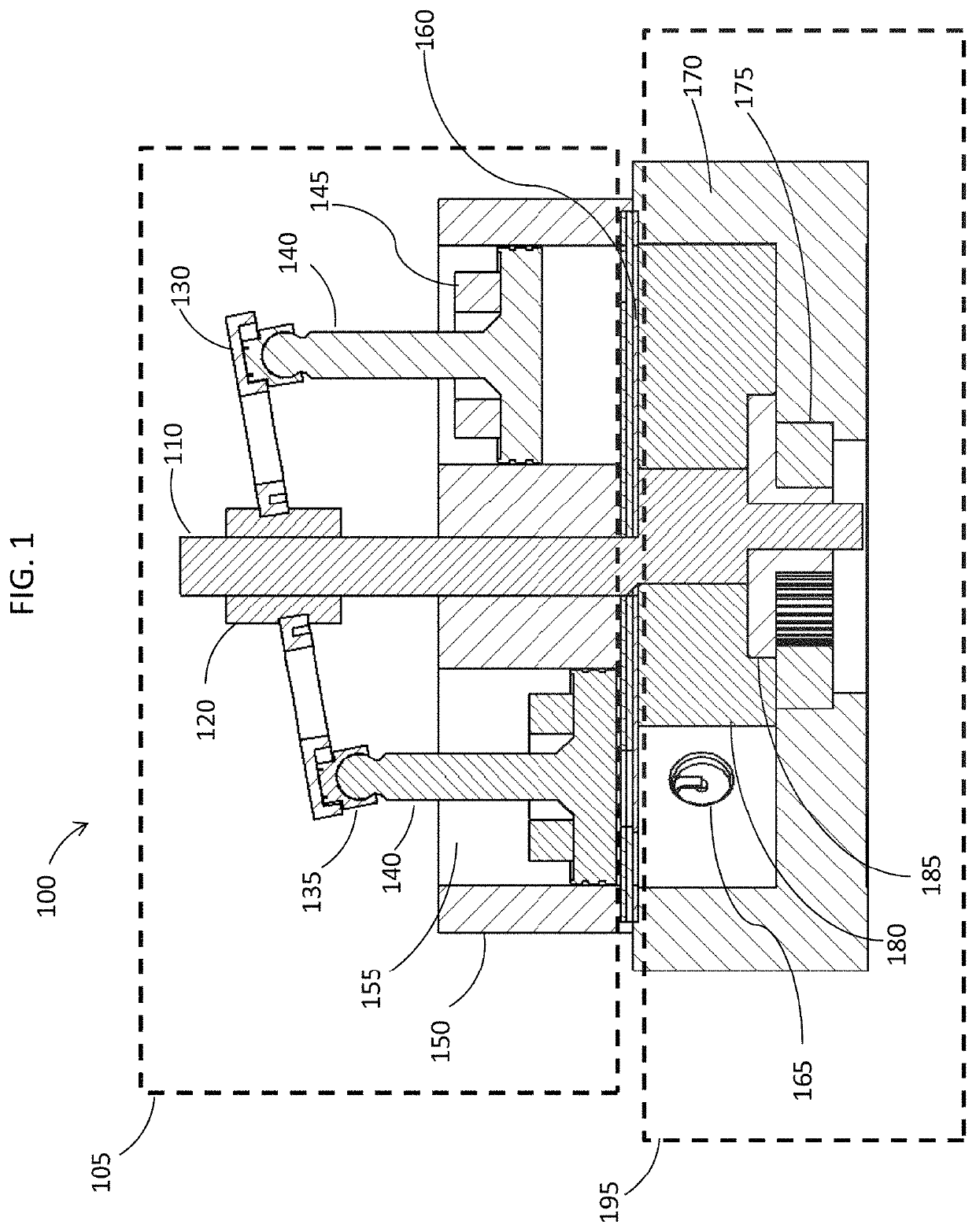
[0037]FIG. 1 shows a cross-sectional view of a split-cycle engine 100 according to the invention. Variable compressor 105 performs the engine intake and compression strokes, and rotary motor 195 performs the expansion and exhaust strokes. Passage valve system 160 regulates the flow of working fluid from variable compressor 105 to rotary motor 195, and the flow of exhaust gases in the reverse direction through the valve system and cylinder 155, and ultimately out of the engine.

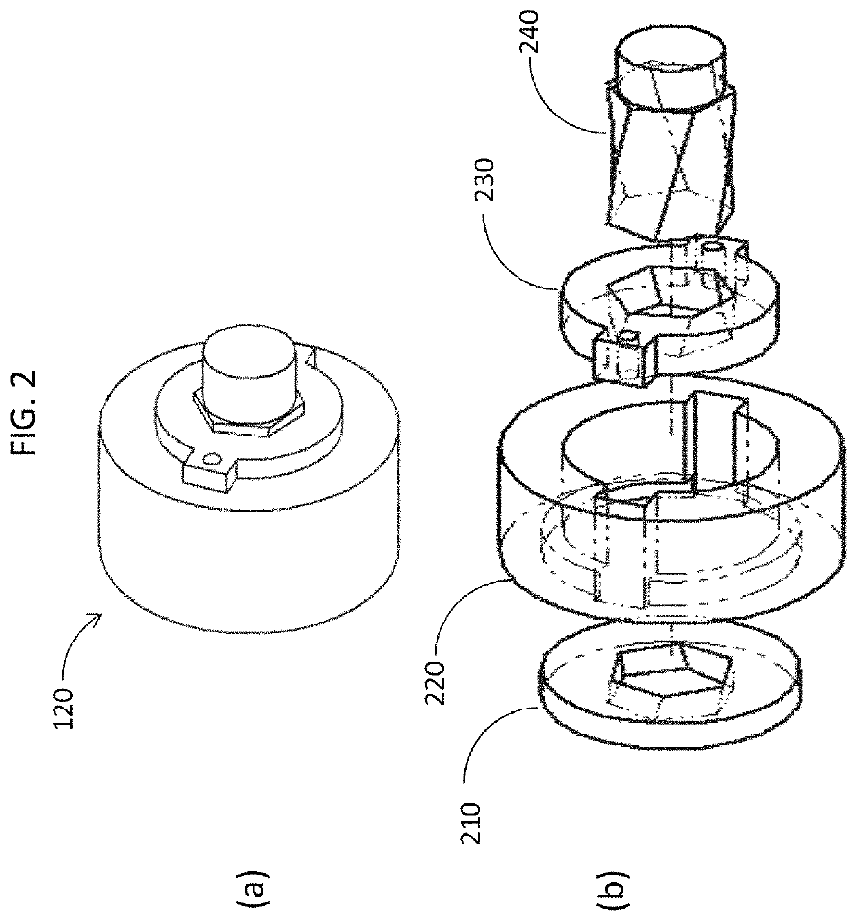
[0038]Rotating shaft 110 is connected to a phase adjustment mechanism 120 and to a stroke adjustment mechanism which controls the stroke of piston 140, by adjusting the angle of tilted swash plate 130. The latter is connected by a slipper 135 to piston 140 which moves inside cylinder block 150, as shaft 110 rotates. The stroke adjustment mechanism is not shown explicitly in FIG. 1, as many designs for this mechanism are familiar to those skilled in the art of engine design.

[0039]On intake, piston 140 slides in ...

second embodiment

[0063]FIG. 9 is a cross-sectional view of a split-cycle engine 800 according to the invention. FIG. 9 uses the same reference numbers as FIG. 1 for like components. In FIG. 9, rotating shaft 110 is connected to a stroke adjustment mechanism 820, which controls the extension of rocker arm 830. Rocker arm 830 is mounted on rocker fork 835 and is connected to piston 140, causing the piston to move up and down inside cylinder 155, as shaft 110 rotates.

[0064]FIG. 10 is a side view of exemplary stroke adjustment mechanism 820 of FIG. 9. Yoke 820, which surrounds rotating shaft 110, has a spiral groove 825. Rocker arm 830 moves along spiral groove 825 as shaft 110 rotates. The axial height of yoke 820 on shaft 110 may be varied in order to change the extension of rocker arm 830, and thus to change the effective travel of piston 140 inside cylinder 155.

[0065]It should be noted that the embodiments of the invention may require additional peripheral systems such as a carburetor, fuel injector...


PUM


Abstract

A split-cycle internal combustion engine includes a variable displacement compressor having two or more cylinders, an adjustment mechanism for varying the displacement volume of the compressor and possibly the phase between the compressor and the motor, and a rotary motor having two or more expansion chambers. A passage valve system located between the compressor and the motor transfers working fluid and combustion exhaust products, and, in addition, mechanically and thermally isolates the compressor from the high pressures and temperatures present in the motor.

Description

CROSS REFERENCES TO RELATED APPLICATIONS[0001]This application is related to and claims priority from commonly owned U.S. Provisional Patent Application 62 / 366,125, entitled: “Variable displacement variable compression ratio split cycle internal combustion engine”, filed on Jul. 25, 2016, the disclosure of which is incorporated by reference in its entirety herein.TECHNICAL FIELD AND BACKGROUND[0002]This invention relates to internal combustion engines and specifically to split-cycle engines with a variable displacement compressor and a rotary motor.[0003]The theoretical thermal efficiency of an internal combustion engine depends primarily on compression ratio, and is highest when the compression ratio is as high as can be achieved under limitations imposed by ambient conditions, such as pressure and temperature of the surrounding air, and limitations imposed by the fuel, such as the danger of spontaneous fuel ignition at overly high compression ratios. Thus, an engine designed to ha...

Claims


Application Information

Patent Timeline
Patent Type & Authority Patents(United States)
IPC IPC(8): F02B53/08F01B3/00F01C1/22F02B33/36F01L7/02F02B75/26F01C11/00F01B21/04F01L1/34F01L7/06F01L7/14F02B33/20F02B55/16
CPCF02B53/08F01B3/00F01B3/007F01B21/04F01C1/22F01C11/008F01L1/34F01L7/02F01L7/06F01L7/14F02B33/20F02B33/36F02B55/16F02B75/26F05C2251/048Y02T10/12
Inventor TENENBAUM, JONATHAN AVRAHAM
Owner TENENBAUM JONATHAN AVRAHAM
Learn More