Eureka AIR delivers breakthrough ideas for toughest innovation challenges, trusted by R&D personnel around the world.

Housing, in particular filter housing and air conditioning system for a vehicle

Active Publication Date: 2020-12-22
HANON SYST
View PDF12 Cites 0 Cited by
  • Summary
  • Abstract
  • Description
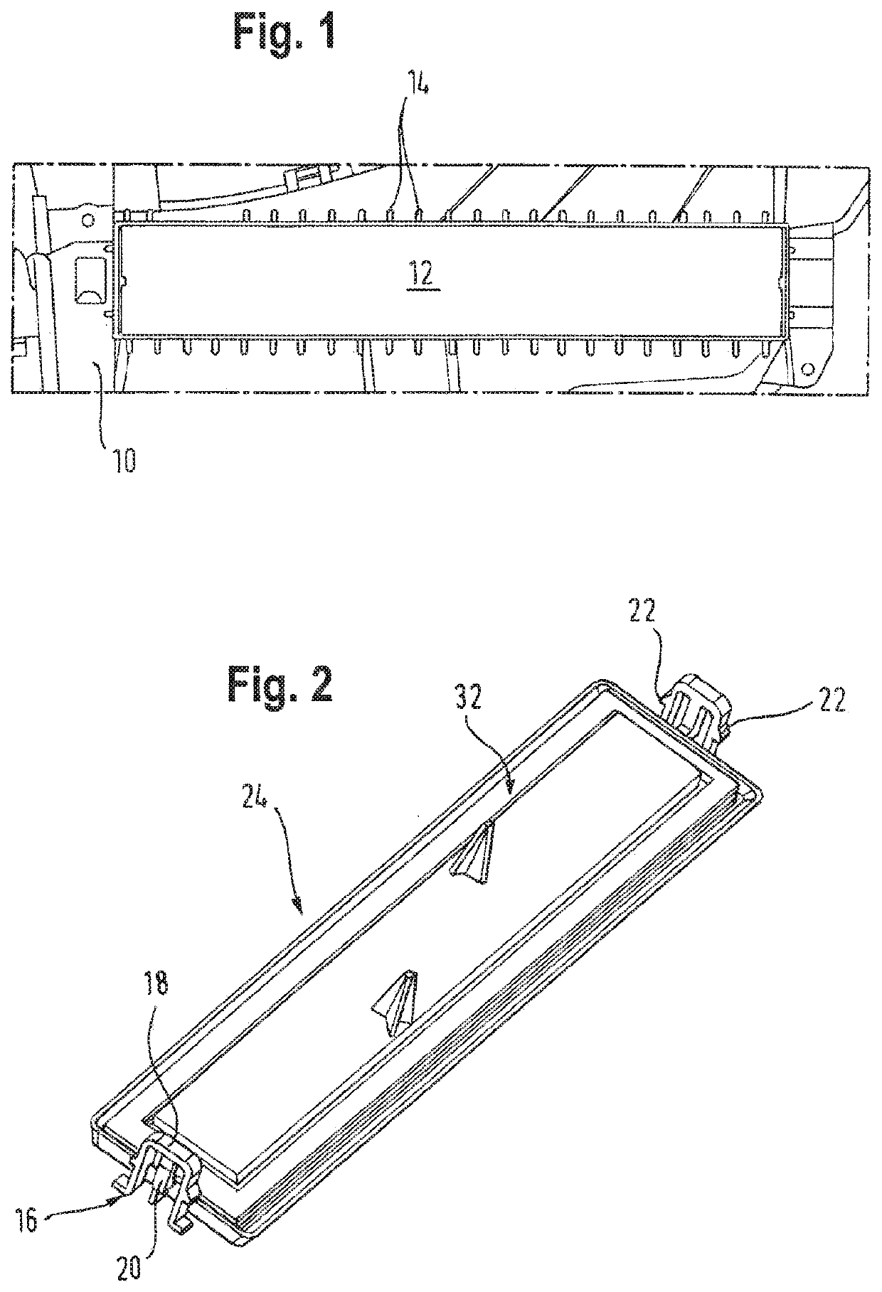
  • Claims
  • Application Information

AI Technical Summary

Benefits of technology

[0010]In the filter housing sealing can hereby be effectively ensured precisely at that site at which the increased pressure and / or moisture occurs. Thereby that a radial, specifically a seal effectively acting laterally from inside against the edge of the filter housing is involved, only minimal forces are required for securing the cap. It has in particular been found that separate securement elements can be omitted. Furthermore, those disadvantages are avoided that result from the fact that the comparatively small cap is subject to deformation over the course of its service life, which applies especially to its outer side. In contrast, the filter housing is comparatively permanently rigid and does not become deformed in its essential circumference as is also the case regarding the inner side of the cap such that the sealing is developed between said two, comparatively durably dimensionally-stable components and can ensure long-lasting sealing.
[0011]Thereby that the seal is provided on the cap, for one, an advantage is obtained to the effect that, should it become damaged, it can be more readily replaced than if the seal were provided on the housing. The filter housing, furthermore, typically has a more complex form than the cap such that any tools and molds that are required for the integration of the seal into the cap, are markedly less complex than if the seal were provided on the filter housing.
[0013]It is preferred that the seal is at least partially implemented of a thermoplastic elastomer. Such a comparatively elastic and flexible material can be deformed without any problem such that the seal in the emplaced state of the cap is reliably and durably in contact on the inner face of the filter housing in the proximity of the opening edge.
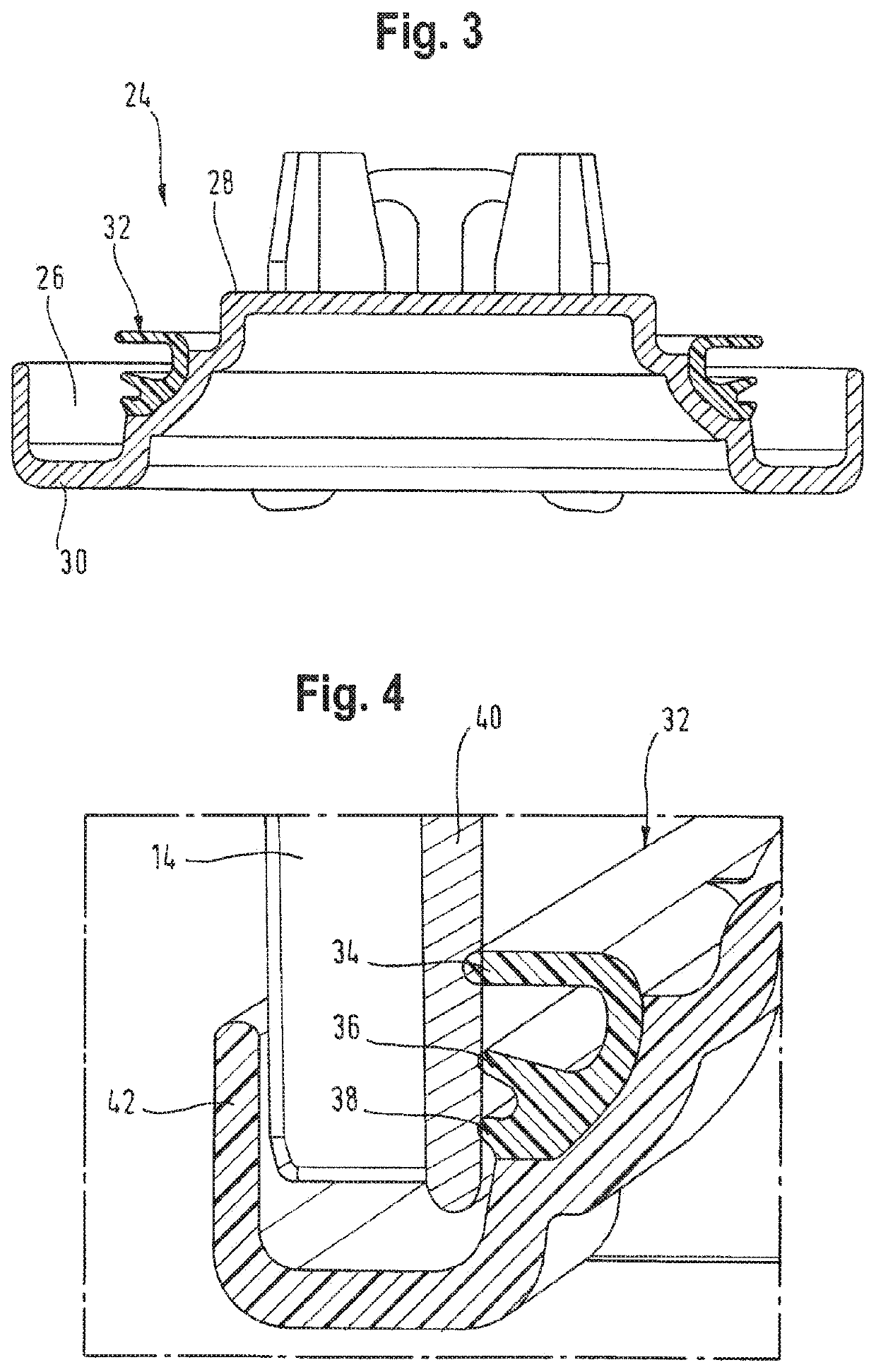
[0015]Special reliability and security of the sealing is obtained if the seal comprises at least one sealing lip, preferably two or more and, especially preferred, three sealing lips. At least one sealing lip extends at least largely in the radial direction, i.e. at least largely parallel to the above described plane defined by the opening edge.
[0016]Special advantages are obtained if at least one sealing lip is more readily deformable than at least one additional sealing lip. Stated differently, by being shaped longer and / or thinner at least one sealing lip is softer than at least one other sealing lip. Even though the material of the individual sealing lips can be different, it is preferred for them to be implemented of the same material and for the seal overall to be unitary. The softer sealing lip involves preferably the innermost sealing lip which, for this purpose, can be developed longer and / or thinner than at least one other sealing lip. This sealing lip can hereby be especially easily deformable and, according to the preferred shaping, ensure the sealing against moisture far in the interior of the filter housing. The at least one more rigid sealing lip is shorter and / or more compactly implemented such that it becomes deformed less significantly in the axial, and primarily in the radial, direction. Stated differently, such a sealing lip is typically compressed in its direction of extension and can consequently ensure the reliable sealing.
[0017]The cap preferably comprises at its outer margin a substantially U-shaped channel in which an opening edge can be received. The opening edge can hereby be clasped especially reliably and securely and the cap can support itself outside on the housing in particular by its outer shank. This can especially advantageously take place in cooperation with the subsequently described projections, ribs or other discrete effective areas. Through the U-shaped channel, i.e. a groove, the continuous securement of the seal can be ensured, simultaneously discrepancies in the geometry of the opening and / or of the cap can be compensated and the sealing function can be ensured.

Problems solved by technology

Such seals, for one, have the disadvantage that, in order to raise the comparatively high forces required for their application, means for securing the cap on the filter housing are necessary that are distinct from the cap proper.
This disadvantage applies equally to known, so-called, radial seals that function outside of the filter housing and, outside of the filter housing, act effectively from the outside laterally onto the described circumferential edge of the filter housing.

Method used


Image

  • Housing, in particular filter housing and air conditioning system for a vehicle
  • Housing, in particular filter housing and air conditioning system for a vehicle

Examples


Embodiment Construction

[0006]Against this background the invention addresses the problem of providing a housing, in particular a filter housing, with a simply implemented cap which best meets the described requirements in view of leak tightness.

[0007]The problem is resolved, for one, through the housing described in Patent Claim 1.

[0008]Accordingly, this housing comprises at least one opening and at least one cap, that can also be referred to as a lid, which comprises at its inner side a seal such that the seal, after the cap has been placed into the opening and covers it, is preferably completely disposed within the housing. It should be emphasized in this context that the subject matter of the invention can be any housing, preferably that of an air-conditioning device. It is, however, preferred that through said opening, for example in the air inlet, in the evaporator housing or the like, a filter is accessible such that the housing according to the invention can be regarded to be a filter housing. In t...


PUM

PropertyMeasurementUnit
thermoplasticaaaaaaaaaa
pressureaaaaaaaaaa
forcesaaaaaaaaaa

Abstract

A housing for a motor vehicle comprises at least one opening and at least one cap which comprises a seal on an inner side such that the seal is disposed within the housing of the air-conditioning device when the cap caps the opening.

Description

[0001]This application claims priority under 35 USC § 119 from German Patent Application No. 102017209578.4 filed on Jun. 7, 2017, hereby incorporated in reference in its entirety for all purposes.FIELD OF THE INVENTION[0002]The invention relates to a housing, in particular a filter housing, and an air-conditioning system for a motor vehicle.[0003]Air-conditioning systems of motor vehicles frequently comprise a pollen and / or odor filter that is disposed in a housing and needs to be replaced regularly. The appropriate housing typically includes for this purpose an opening through which the filter can be removed. The opening is closed by a cap which, for one, with respect to the housing, must be sealed tightly such that it withstands the pressure in the air-conditioning system that is comparatively higher than the ambient pressure. Depending on the location of this opening, the cap, for another, must ensure leak tightness against water occurring in the air-conditioning system.PRIOR AR...

Claims


Application Information

Patent Timeline
Patent Type & Authority Patents(United States)
IPC IPC(8): B01D46/00B01D46/10B01D46/24B60H3/06
CPCB01D46/0002B60H3/0658B01D46/10B01D46/0006B01D46/2414B60H2003/065B01D2271/02B60H3/06B60H3/0616B60H1/00514B01D46/0004B60H2001/00635
Inventor ALBERTERNST, THOMASHOPPEN, JÜRGEN
Owner HANON SYST
Why Eureka
Eureka Blog
Learn More