
Method for preventing spills resulting from pipeline failures

a pipeline and failure technology, applied in the field of pipelines, can solve the problems of severe damage, difficult and expensive cleanup and remediation, and is impossible to completely remediate, and achieve the effect of reducing the risk of spills and high level of assuran

Active Publication Date: 2020-12-15
SAFE CROSSINGS
View PDF6 Cites 2 Cited by
  • Summary
  • Abstract
  • Description
  • Claims
  • Application Information

AI Technical Summary

Benefits of technology

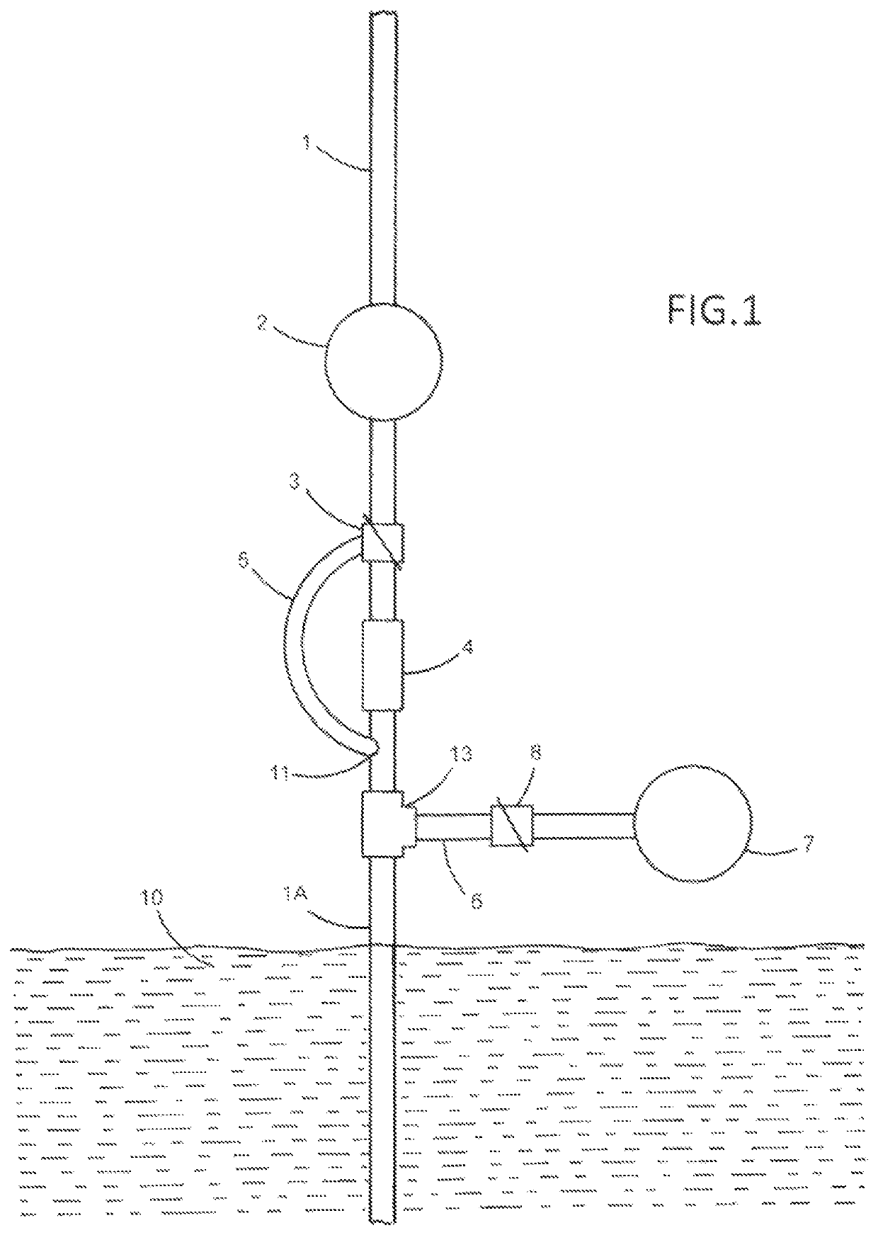
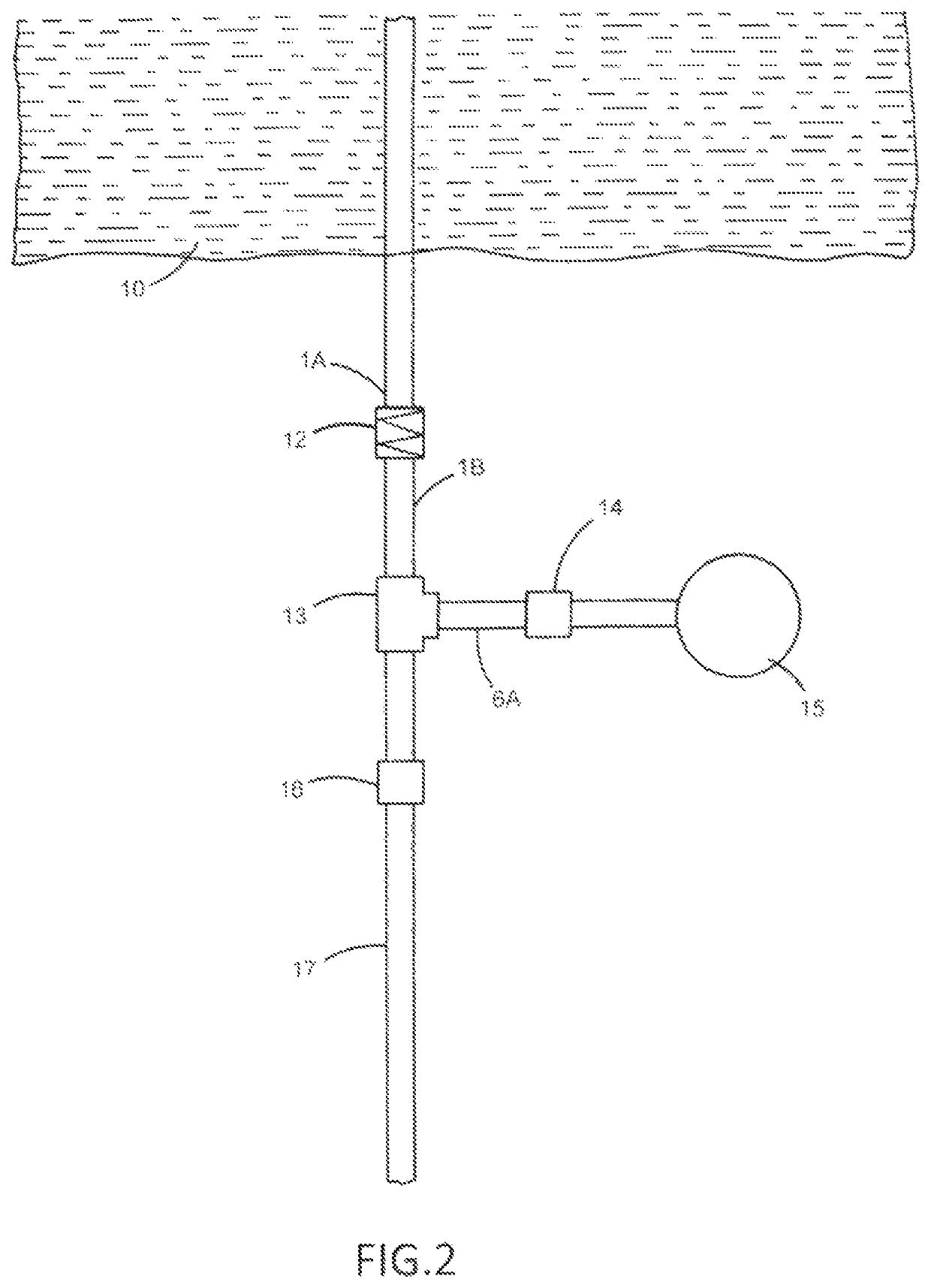
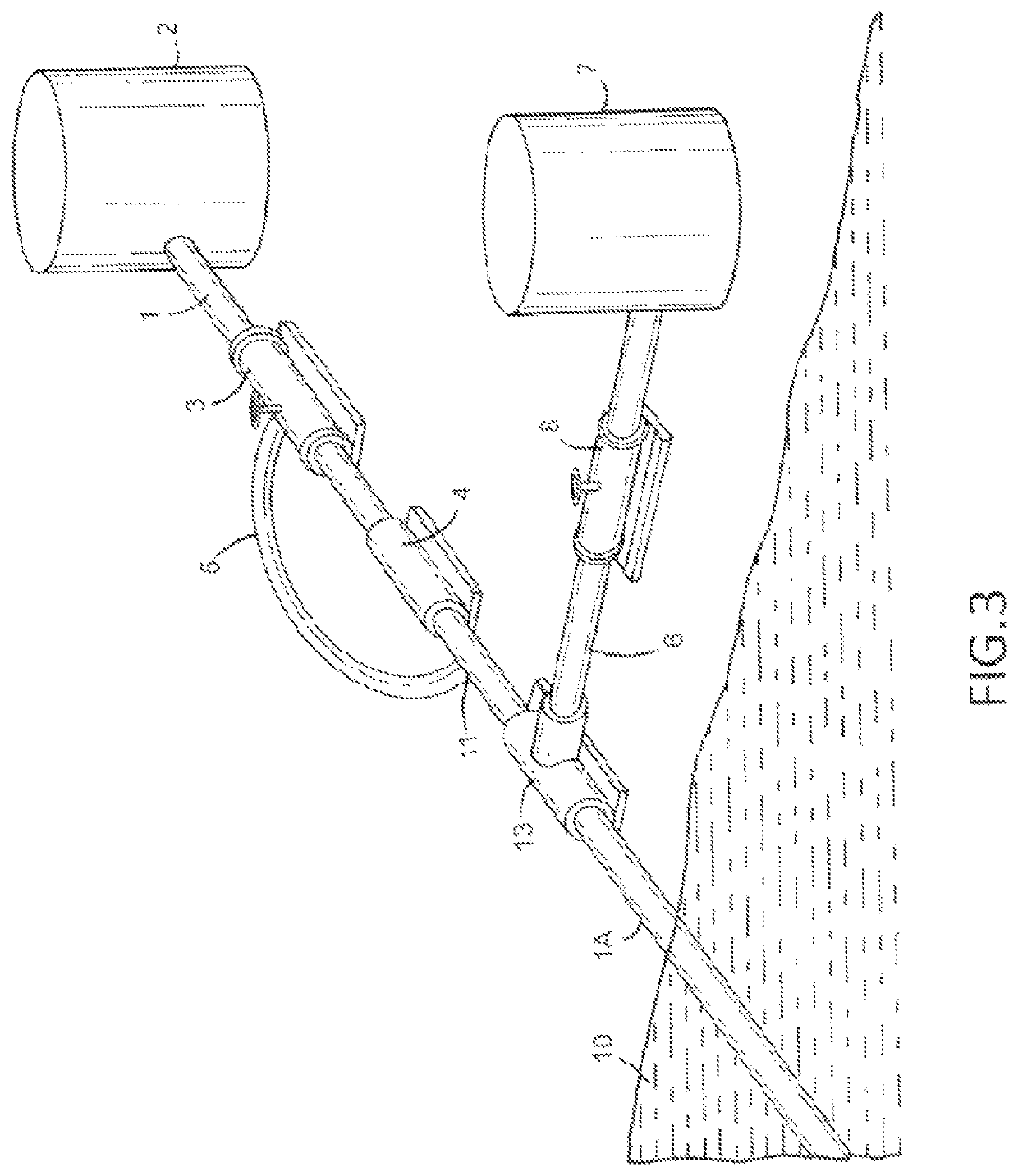
The system described in this patent can reduce the risk of spills and prevent contamination or environmental damage caused by breaches in pipeline segments. It includes a tank that can store and later dispose of contaminated material, preventing it from being carried on downstream. The tank is connected to the pipeline through a normally closed valve and a normally open valve. In the event of a breach, the normally closed valve would be opened to allow material to be pumped into the tank, while the normally open valve would be closed to prevent further transport of material downstream.

Problems solved by technology

These pipelines cross over a variety of natural features, including features which could be severely damaged in the event of spills resulting from breaches of the pipeline.
In these areas, cleanup and remediation would be particularly difficult and expensive, and would likely be impossible to completely remediate.
Many of the pipeline sections crossing such sensitive areas are not modified to reduce the risk of spills or to minimize the environmental damage that would result from such spills.
Several incidents of damaging spills have occurred over the past several years, and a great deal of concern has been expressed about other areas in which the failure of a pipeline would wreak potentially catastrophic environment damage.
The transported material will not be discharged into the environment in the protected section; rather, the material in the protected section will be drawn into the pipeline, contaminating the transported material, but not the environment.

Method used


Image

  • Method for preventing spills resulting from pipeline failures
  • Method for preventing spills resulting from pipeline failures
  • Method for preventing spills resulting from pipeline failures

Examples


Embodiment Construction

[0024]As required, detailed embodiments of the present invention are disclosed herein. However, it is to be understood that the disclosed embodiments are exemplary only, and the invention may be embodied in various forms, especially so as to provide optimal performance in various environments and applications. The accompanying drawings are not intended to be to scale, and features may be exaggerated or minimized in order to best depict the system herein described. Therefore, the details disclosed herein are not to be interpreted as limiting, but merely as a representative basis for teaching one skilled in the art to variously employ the present invention.

[0025]Referring now to the drawings, wherein the numerals refer to the various features of the system, composed of various parts that comprise the whole.

[0026]As disclosed in this patent application, the system is comprised of an upstream and a downstream portion of the system.

[0027]The upstream portion is comprised of a restrictor,...


PUM

PropertyMeasurementUnit
pressureaaaaaaaaaa
internal pressureaaaaaaaaaa
distancesaaaaaaaaaa

Abstract

A petroleum pipeline safety system for preventing contamination of an environmentally sensitive area close to a pipeline includes an upstream portion of the pipeline supplying a flow of fluid material, a crossing portion of the pipeline receiving the flow of fluid material from the upstream portion and conveying the flow of fluid material through the environmentally sensitive area to a downstream portion of the pipeline, the downstream portion, a pipeline pressure activated valve selectively capable of blocking the flow of fluid material from entering the crossing portion based upon a change in pressure within the crossing portion, and a fluid capacitor connected to the upstream portion configured to filter out a pressure spike in the upstream portion associated with the valve blocking the flow of fluid material.

Description

CROSS-REFERENCE TO RELATED APPLICATIONS[0001]This disclosure is a continuation-in-part application of U.S. patent application Ser. No. 15 / 817,245 filed on Nov. 19, 2017 which claims priority to U.S. Provisional Patent Application 62 / 424,444, filed on Nov. 19, 2016, both of which are hereby incorporated by reference.FIELD OF INVENTION[0002]The present invention relates to the field of fluid transfer and transportation systems, specifically pipelines, and methods to reduce the risk of leakage and resulting loss of transported material and / or environmental damage in the event of a breach of the pipeline.BACKGROUND OF THE INVENTION[0003]The statements in this section merely provide background information related to the present disclosure. Accordingly, such statements are not intended to constitute an admission of prior art.[0004]Many fluid materials, including petroleum and petroleum products, are transported over long distances through pipelines. These pipelines cross over a variety of...

Claims


Application Information

Patent Timeline
Patent Type & Authority Patents(United States)
IPC IPC(8): F17D5/02F17D1/14G01M3/28F16L58/10F17D5/00
CPCF16L58/1009F17D5/005F17D5/00F17D5/02F17D1/14G01M3/2815Y10T137/7727Y10T137/0452F16L2201/30Y10T137/7762G05B2219/31356B67D7/3218F16K17/02F16L55/1022F16K17/34B67D7/3209F16K31/12E21B43/0122G05D16/16F15B20/005
Inventor MORETZ, R. DALE
Owner SAFE CROSSINGS
Learn More