Method and apparatus for communication in wireless mobile communication system

a wireless mobile communication and wireless technology, applied in power management, transmission path division, high-level techniques, etc., can solve the problems of rapid consumption of terminal power and difficulty in meeting the requirements of the next-generation mobile communication system requiring a low latency, and achieve high data rate, low cost, and high speed

Active Publication Date: 2020-12-08
SAMSUNG ELECTRONICS CO LTD
View PDF16 Cites 10 Cited by
  • Summary
  • Abstract
  • Description
  • Claims
  • Application Information

AI Technical Summary

Benefits of technology

[0011]If a terminal successively receives and identifies signals of a base station, terminal power is rapidly consumed. It is important to reduce such power consumption. Accordingly, the terminal may be switched (transition) from a radio resource control (RRC) connected mode to an RRC idle mode to be in a standby mode. However, many signaling procedures are necessary in order for the terminal in the standby mode to be switched to the RRC connected mode again.
[0019]According to the aspect of the present disclosure, in the next-generation mobile communication system, the handover procedure using carrier aggregation technology can be used, and, thus, a terminal can transmit and receive data without time interference during the handover operation.

Problems solved by technology

If a terminal successively receives and identifies signals of a base station, terminal power is rapidly consumed.
If many terminals in the RRC inactive mode exist in the network, this may cause the signaling overhead due to the procedure for periodically updating the periodic RAN notification area, and thus it is necessary for the network to manage the terminals in the RRC inactive mode and, if needed, to switch (transition) the terminals in the RRC inactive mode to the RRC idle mode.
In a case of performing the above-described operation, time interference occurs in the handover procedure, and it becomes difficult to satisfy the requirements of the next-generation mobile communication system requiring a low latency.

Method used


Image

  • Method and apparatus for communication in wireless mobile communication system
  • Method and apparatus for communication in wireless mobile communication system
  • Method and apparatus for communication in wireless mobile communication system

Examples


embodiment 1

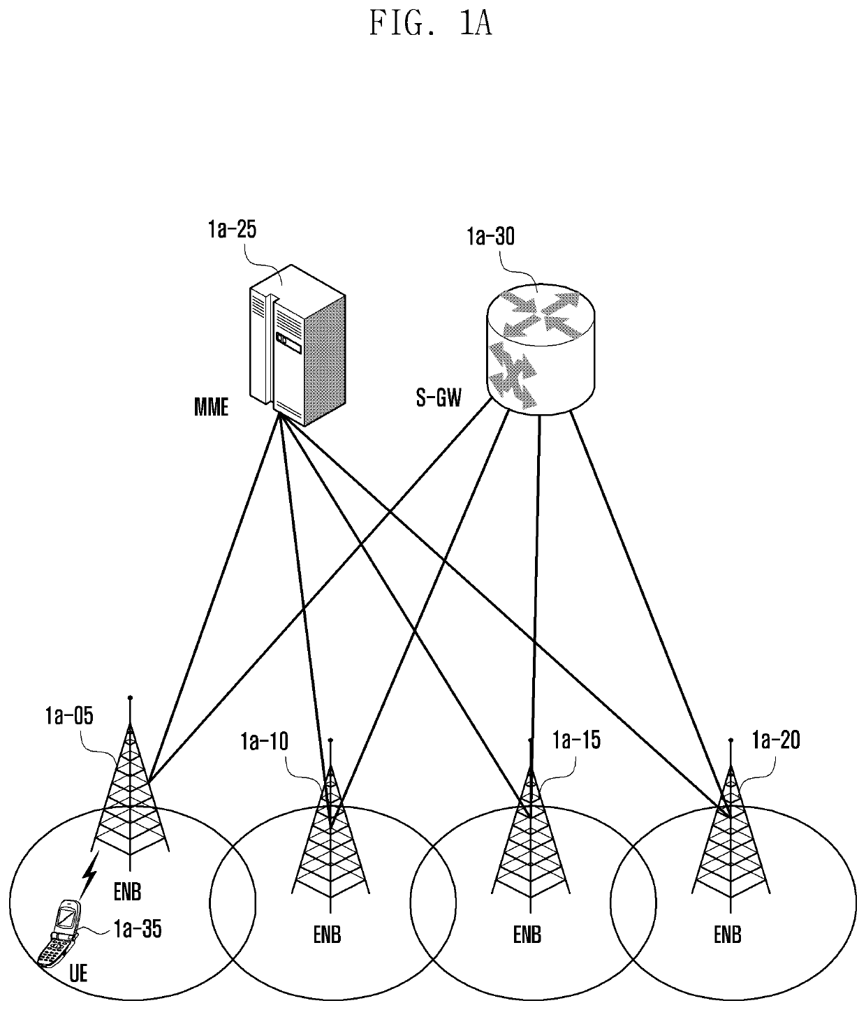
[0092]FIG. 1A is a diagram of an LTE system, according to an embodiment of the present disclosure.

[0093]Referring to FIG. 1A, a RAN of an LTE system includes evolved node Bs (“eNBs”“ENBs, “node Bs”, or “base stations”) 1a-05, 1a-10, 1a-15, and 1a-20, a mobility management entity (MME) 1a-25, and a serving-gateway (S-GW) 1a-30. User equipment (“UE” or “terminal”) 1a-35 accesses to an external network through the ENBs 1a-05, 1a-10, 1a-15, and 1a-20 and the S-GW 1a-30.

[0094]The ENBs 1a-05, 1a-10, 1a-15, and 1a-20 correspond to an existing node B of a universal mobile telecommunications system (UMTS). The ENBs 1a-05, 1a-10, 1a-15, or 1a-20 are connected to the UE 1a-35 on a radio channel, and play or serve a more complicated role than that of the existing node B. In the LTE system, since all user traffics including a real-time service, such as a voice over internet protocol (VoIP) through an internet protocol, are serviced on shared channels, devices performing scheduling through summar...

embodiment 2

[0240]FIG. 2A is a diagram of an LTE system, according to an embodiment of the present disclosure.

[0241]Referring to FIG. 2A, as illustrated, a RAN of an LTE system includes ENBs 2a-05, 2a-10, 2a-15, and 2a-20, an MME 2a-25, and an S-GW 2a-30. “UE 2a-35 accesses to an external network through the ENBs 2a-05, 2a-10, 2a-15, and 2a-20 and the S-GW 2a-30.

[0242]In FIG. 2A, the ENB 2a-05, 2a-10, 2a-15, and 2a-20 correspond to an existing node B of a UMTS system. The ENBs 2a-05, 2a-10, 2a-15, or 2a-20 are connected to the UE 2a-35 on a radio channel, and plays a more complicated role than that of the existing node B. In the LTE system, since all user traffics including a real-time service, such as a VoIP through an internet protocol, are serviced on shared channels, devices performing scheduling through consolidation of state information, such as a buffer state, an available transmission power state, and a channel state of each UE, are necessary, and the ENBs 2a-05, 2a-10, 2a-15, and 2a-20...

embodiment 3

[0412]FIG. 3A is a diagram of an LTE system, according to an embodiment of the present disclosure.

[0413]A RAN of an LTE system includes ENBs 3a-05, 3a-10, 3a-15, and 3a-20, an MME 3a-25, and an S-GW 3a-30. A UE 3a-35 accesses to an external network through the ENBs 3a-05, 3a-10, 3a-15, and 3a-20 and the S-GW 3a-30.

[0414]In FIG. 3A, the ENBs 3a-05, 3a-10, 3a-15, and 3a-20 correspond to an existing node B of a UMTS system. The ENB 3a-05 is connected to the UE 3a-35 on a radio channel, and plays a more complicated role than that of the existing node B. In the LTE system, since all user traffics including a real-time service, such as a VoIP through an internet protocol, are serviced on shared channels, devices performing scheduling through consolidation of state information, such as a buffer state, an available transmission power state, and a channel state of each UE, are necessary, and the ENBs 3a-05, 3a-10, 3a-15, and 3a-20 correspond to such scheduling devices. One ENB controls a plu...


PUM


Abstract

The present disclosure relates to a communication method and system for converging a 5th-Generation (5G) communication system for supporting higher data rates beyond a 4th-Generation (4G) system with a technology for IoT, and may be applied to intelligent services based on the 5G communication technology and the IoT-related technology, e.g., smart home, smart building, smart city, smart car, connected car, health care, digital education, smart retail, security and safety services.A method by a terminal in a wireless communication system is provided, and includes receiving, from a base station, a paging message for switching a mode of the terminal in an RRC inactive mode to an RRC idle mode, transmitting an RRC message to the base station based on the paging message, receiving an RRC-connection release message (CRR) from the base station, and transitioning from the RRC inactive mode to the RRC idle mode based on the RRC-CRR.

Description

PRIORITY[0001]This application claims priority under 35 U.S.C. § 119(a) to Korean Patent Application Serial No. 10-2017-0007142, which was filed in the Korean Intellectual Property Office on Jan. 16, 2017, and Korean Patent Application Serial No. 10-2017-0029284, which was filed in the Korean Intellectual Property Office on Mar. 8, 2017, the entire content of each of these applications is incorporated herein by reference.BACKGROUND1. Field of the Disclosure[0002]The present disclosure relates, generally, to a method and an apparatus in a wireless mobile communication system, and more particularly, to a method and an apparatus for configuring a packet data convergence protocol (PDCP) and a radio link control (RLC) header format in a next-generation mobile communication system.[0003]Further, the present disclosure relates to a new method and apparatus for changing an operation mode of a terminal in a next-generation mobile communication system.[0004]Further, the present disclosure rel...

Claims


Application Information

Patent Timeline
Patent Type & Authority Patents(United States)
IPC IPC(8): H04W36/00H04W76/28H04W76/27H04W74/00H04L5/00H04W52/02H04W76/30
CPCH04W36/0088H04W36/0055H04L5/0091H04W74/002H04W76/27H04W36/0033H04W36/0038H04L5/0007H04L5/0053H04W76/28H04W36/0016H04W76/30H04L5/0023H04W52/0216H04L5/001H04W36/0072Y02D30/70
Inventor KIM, DONGGUNKIM, SOENGHUNKIM, SANGBUMSAYENKO, ALEXANDERJIN, SEUNGRI
Owner SAMSUNG ELECTRONICS CO LTD
Why Eureka
Try Eureka