Vibration reduction for a magnetic resonance imaging apparatus
a magnetic resonance imaging and electromagnetic force technology, applied in the field of magnetic resonance imaging apparatus, can solve the problems of blurred acquired image, deterioration of image quality, unsatisfactory for patients who are subjects, etc., and achieve the effect of reducing the electromagnetic for
- Summary
- Abstract
- Description
- Claims
- Application Information
AI Technical Summary
Benefits of technology
Problems solved by technology
Method used
Image
Examples
first embodiment
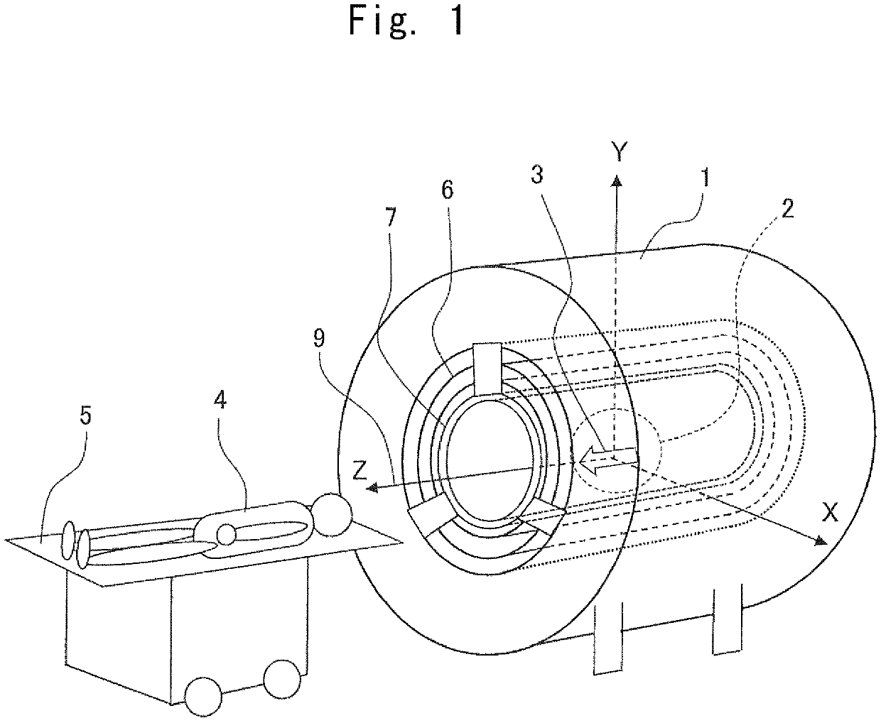
[0028]First, an overall configuration of a magnetic resonance imaging apparatus will be described with reference to FIG. 1. The magnetic resonance imaging apparatus (hereinafter referred to as “MRI apparatus”) includes a cylindrical magnetic pole 1 whose central axis is a Z axis 9 (CL, center line), in which the magnetic pole 1 generates a static magnetic field in an imaging region 2 in the same direction as the Z axis 9 indicated by a void arrow 3 in FIG. 1. A subject 4 is carried to the imaging region 2 by a movable bed 5. The MRI apparatus processes a signal by a computer system (not illustrated) to obtain an image.
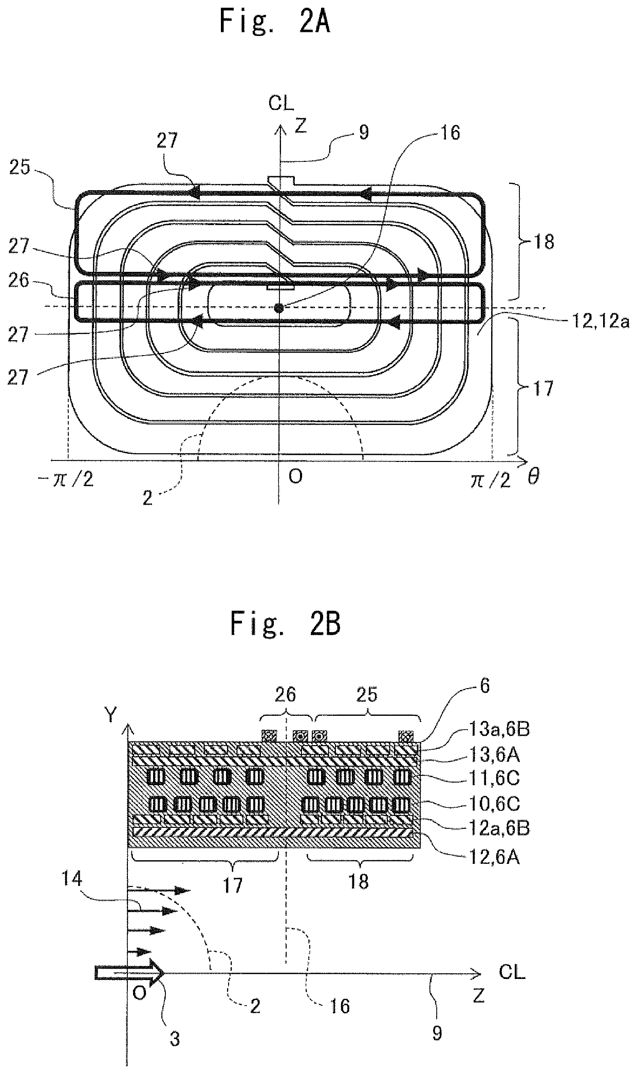
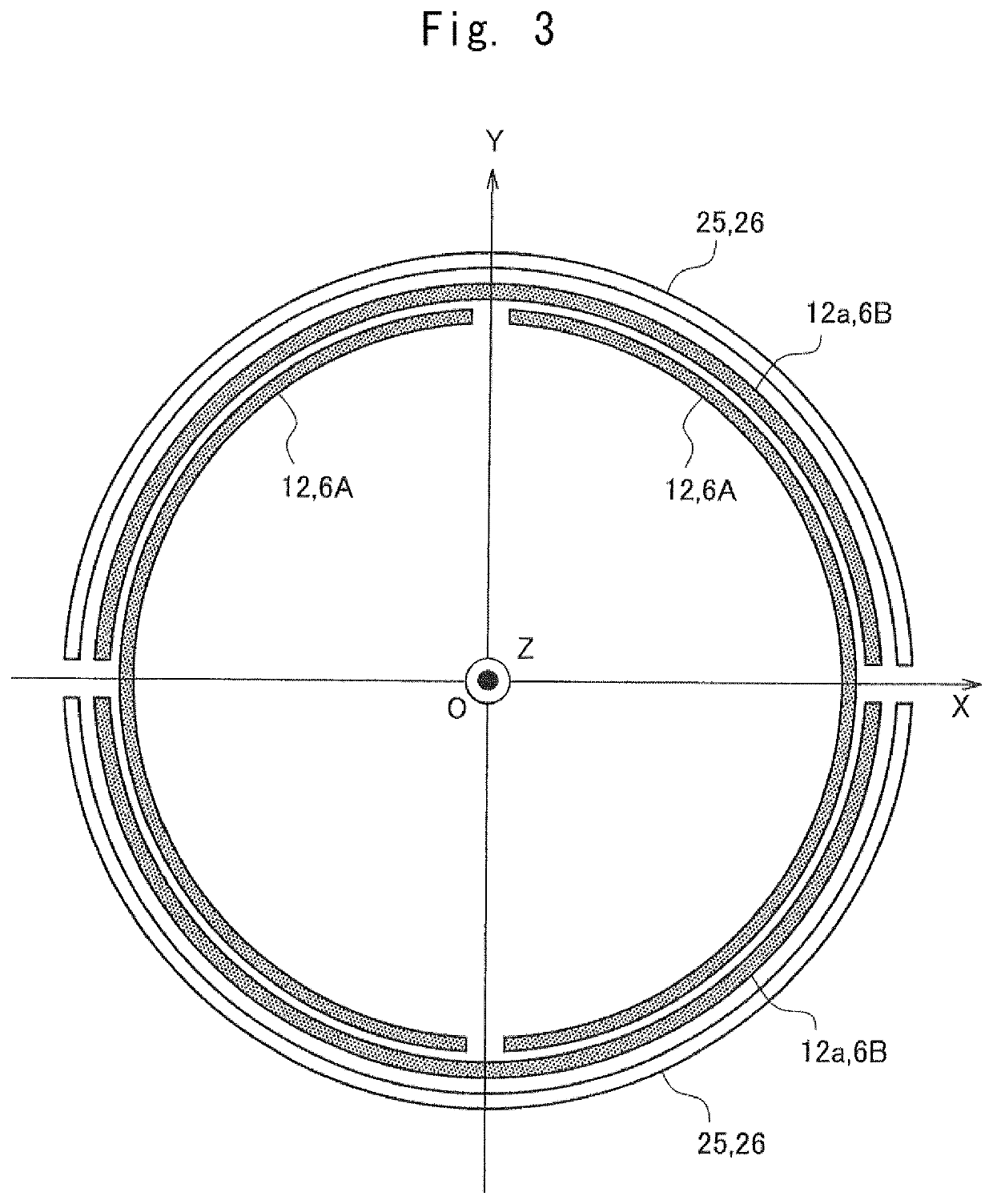
[0029]The MRI apparatus includes a cylindrical gradient magnetic field coil 6 disposed on a radially inner side of the magnetic pole 1 coaxially with the magnetic pole 1, and a cylindrical high frequency coil 7 arranged on a radially inner side of the gradient magnetic field coil 6 coaxially with the magnetic pole 1. The gradient magnetic field coil 6 generates a dynam...
second embodiment
[0053]Next, the MRI apparatus according to the second embodiment will be described with reference to FIG. 8. FIG. 8 is a top view illustrating a wiring structure of an additional coil with respect to the Y direction gradient magnetic field coil of a magnetic resonance imaging apparatus according to the second embodiment of the present invention.
[0054]In the present embodiment, the first additional coil 25 and the second additional coil 26 are formed of one electric current circuit. The first additional coil 25 and the second additional coil 26 share an electric current inflow / outflow path 33 connected to a power supply (not illustrated).
[0055]Each of the first additional coil 25 and the second additional coil 26 includes a conductor that intersects each other at an adjacent portion, and have a shape of approximately number ‘8’. As a result, the electric current circulating direction of the first additional coil 25 and the second additional coil 26 is reversed.
[0056]In the additional...
third embodiment
[0058]Next, the MRI apparatus according to the third embodiment will be described with reference to FIG. 9. FIG. 9 is a top view illustrating a wiring structure of an additional coil with respect to the Y direction gradient magnetic field coil of a magnetic resonance imaging apparatus according to the third embodiment of the present invention.
[0059]In the present embodiment, a third additional coil 34 is provided in addition to the first additional coil 25 and the second additional coil 26. The first additional coil 25, the second additional coil 26, and the third additional coil 34 are formed of one electric current circuit. The first additional coil 25, the second additional coil 26, and the third additional coil 34 share the electric current inflow / outflow path 33 connected to a power supply (not illustrated).
[0060]The first additional coil 25, the second additional coil 26, and the third additional coil 34 include conductors that intersect each other at an adjacent portion. As a...
PUM
 Abstract
Description
Claims
Application Information
 - R&D
- Intellectual Property
- Life Sciences
- Materials
- Tech Scout
- Unparalleled Data Quality
- Higher Quality Content
- 60% Fewer Hallucinations
Browse by: Latest US Patents, China's latest patents, Technical Efficacy Thesaurus, Application Domain, Technology Topic, Popular Technical Reports.
© 2025 PatSnap. All rights reserved.Legal|Privacy policy|Modern Slavery Act Transparency Statement|Sitemap|About US| Contact US: help@patsnap.com


