
Laser welding method

a laser beam and welding method technology, applied in welding apparatus, metal-working equipment, manufacturing tools, etc., can solve the problems of the speed of the scanning operation of the laser beam, and so as to reduce the number of steps necessary for welding prevent or reduce the deformation of the object to be welded, and improve the effect of preventing or reducing the deformation of the object to b

Active Publication Date: 2020-11-24
TOYOTA JIDOSHA KK
View PDF8 Cites 1 Cited by
  • Summary
  • Abstract
  • Description
  • Claims
  • Application Information

AI Technical Summary

Benefits of technology

[0010]In view of the above-described techniques and procedures, an object of the present disclosure is to provide a laser welding method capable of reducing the number of steps necessary for welding an object to be welded while preventing the occurrence of defective welding.
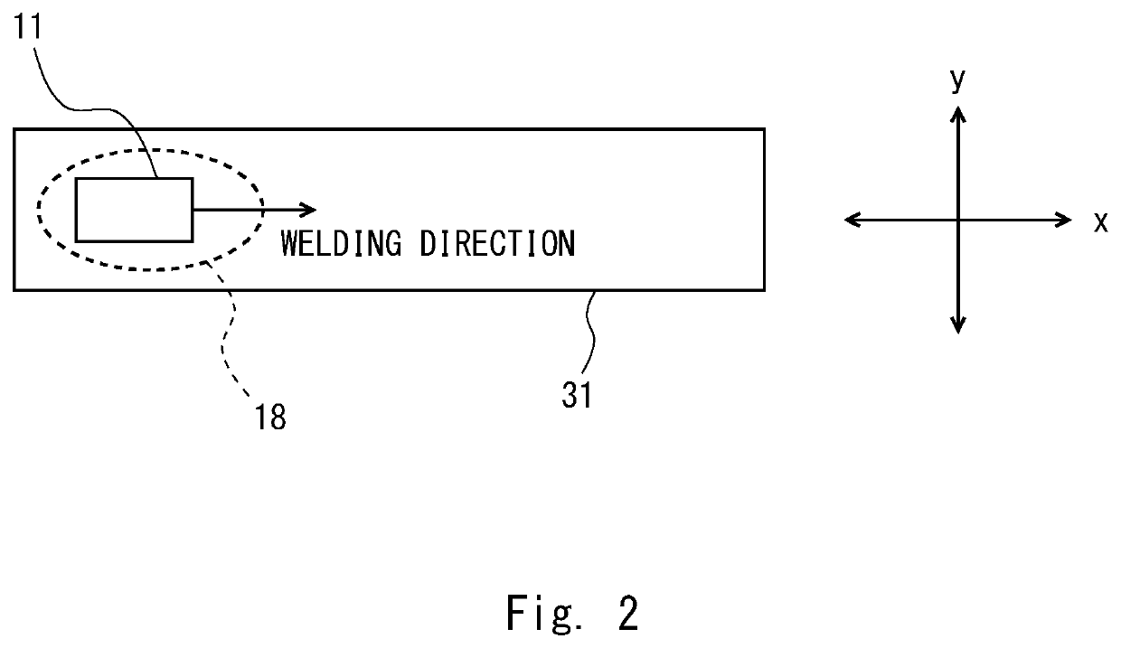
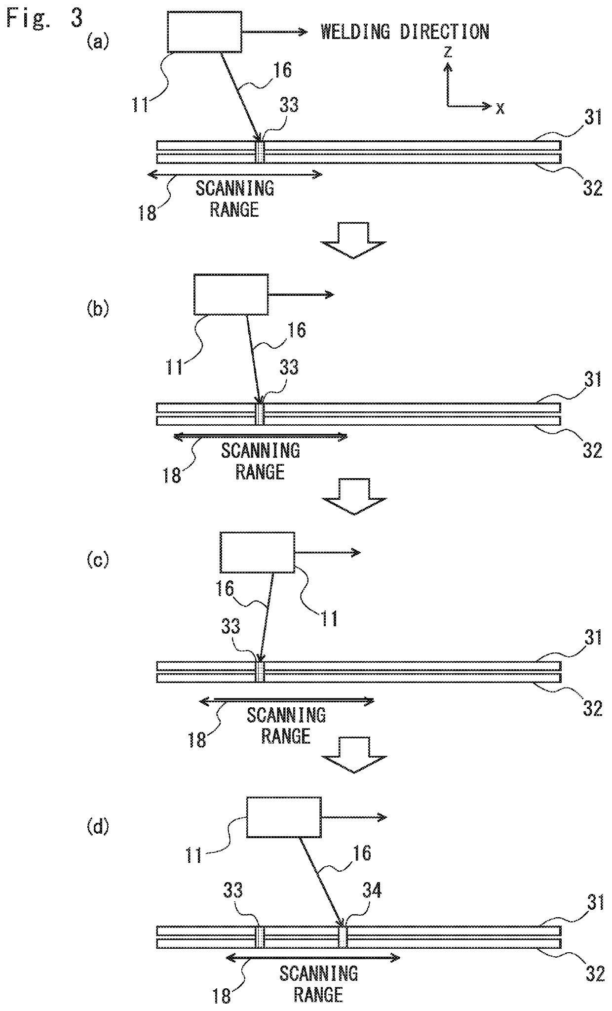
[0012]In the laser welding method according to the present disclosure, the preliminary-fixation welding step and the main welding step for the object to be welded are performed within the scanning range of the scanning unit while moving the scanning unit. That is, both the preliminary-fixation welding and the main welding are performed in the same process. Therefore, the number of times of traveling of the scanning unit (that is, the number of times the scanning unit travels on the welding route) that are necessary when the object to be welded is welded can be reduced to one. Consequently, the number of steps necessary for welding the object to be welded can be reduced. Further, when the object to be welded is welded, the place to be main-welded is main-welded in the state where the place to be main-welded is located between a place that is already main-welded and a place that is already preliminary-fixation-welded (in other words, in a state where both side of the place to be main-welded are restrained). Therefore, the deformation of the object to be welded can be prevented or reduced and hence the occurrence of defective welding can be prevented.
[0013]Further, in the laser welding method according to the present disclosure, two or more places located on the downstream side with respect to the place to be main-welded in the welding direction may be preliminary-fixation-welded. By preliminary-fixation-welding two or more places located on the downstream side with respect to the place to be main-welded in the welding direction as described above, the deformation and the positional deviation can be prevented more reliably.
[0014]Further, in the laser welding method according to the present disclosure, the place to be main-welded may be main-welded so that the place to be main-welded overlaps the place to be preliminary-fixation-welded. By main-welding the place to be main-welded so that the place to be main-welded overlaps the place to be preliminary-fixation-welded as described above, it is possible to prevent various external inputs for the objects to be welded from directly entering the preliminary-fixation-welded place and hence prevent the cause of secondary defects that would otherwise be caused by the rupture of the preliminary-fixation-welded place.
[0015]Further, in the laser welding method according to the present disclosure, the place to be main-welded may be main-welded so that the place to be main-welded is shifted from the preliminary-fixation-welded place in at least one of a direction in parallel with the welding direction and a direction perpendicular to the welding direction. By shifting the place to be main-welded from the preliminary-fixation-welded place as described above, the objects to be welded can be restrained at a place closer to the place to be main-welded when the place to be main-welded is main-welded, and hence the effect for preventing or reducing the deformation of the object to be welded can be improved.
[0017]According to the present disclosure, it is possible to provide a laser welding method capable of reducing the number of steps necessary for welding an object to be welded while preventing the occurrence of defective welding.

Problems solved by technology

Incidentally, when the object(s) to be welded is a plurality of metal plates, there are cases where the objects to be welded are deformed by a thermal distortion, a residual stress, or the like that occurs when the objects to be welded are welded, thus causing defective welding.
Further, the moving operation of the scanning unit performed by the robot is slower than the scanning operation of the laser beam performed by the scanning unit.

Method used


Image

  • Laser welding method
  • Laser welding method
  • Laser welding method

Examples


examples

[0066]Next, examples according to the present disclosure are explained.

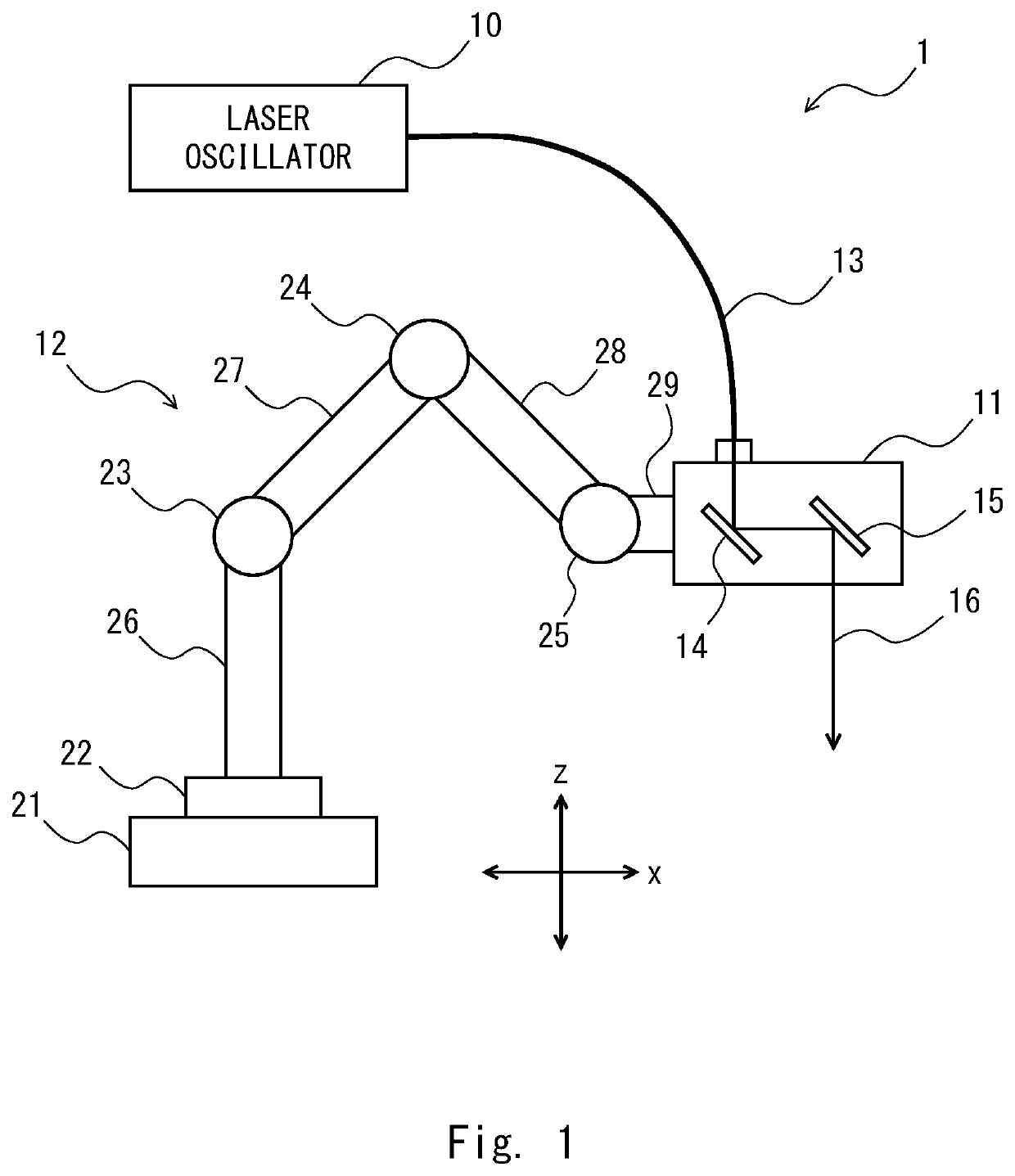
[0067]An object to be welded was welded by using a laser welding method explained above. In this example, two 6000-series aluminum alloy plates placed on each other were used as an object to be welded 100 (see FIG. 10). The thicknesses of the aluminum alloy plates were 1.2 mm and 0.9 mm, respectively. A fiber laser was used as the laser oscillator 10 of the laser welding device 1. The shape of each preliminary-fixation-welded place was a spot shape having a diameter of about 2 mm. Further, the shape of each main-welded place was a spot shape having a diameter of about 7 mm. The speed of the preliminary-fixation welding (i.e., the speed at which a spot shape of preliminary-fixation welding was formed) was about 0.1 seconds. Further, the speed of the main welding (i.e., the speed at which a spot shape of main welding was formed) was about 1.0 seconds.

[0068]In this example, as shown in FIG. 10, 20 places in the obje...


PUM

PropertyMeasurementUnit
diameteraaaaaaaaaa
diameteraaaaaaaaaa
moving speedaaaaaaaaaa

Abstract

A laser welding method for welding a plurality of objects to be welded by applying a laser beam scanned by a scanning unit to the plurality of objects to be welded while moving the scanning unit in a welding direction along a welding path, the laser welding method including the steps of: performing a step of preliminary-fixation-welding on a predetermined place in the welding direction of the objects to be welded, and a step of main-welding on a place corresponding to the preliminarily-fixed place of the object to be welded within a scanning range of the scanning unit while moving the scanning unit. Further, when the place corresponding to the preliminarily-fixed place of the object to be welded is main-welded, the place is main-welded in a state where both sides of the place to be main-welded are restrained.

Description

INCORPORATION BY REFERENCE[0001]This application is based upon and claims the benefit of priority from Japanese patent application No. 2015-029629, filed on Feb. 18, 2015, the disclosure of which is incorporated by reference herein in its entirety.BACKGROUND[0002]1. Field[0003]The present disclosure relates to a laser welding method.[0004]2. Description of Related Art[0005]Remote welding may be performed by scanning (i.e., directing in various directions in an orderly manner) a laser beam guided from a laser oscillator by using a scanning unit and applying the scanned (i.e., directed) laser beam to an object(s) to be welded.[0006]Japanese Unexamined Patent Application Publication No. 2006-007238 discloses a technique relating to remote welding. In the technique disclosed in Japanese Unexamined Patent Application Publication No. 2006-007238, a plurality of objects to be welded are preliminarily-fixed before they are laser-welded. This can prevent the positions of the plurality of obj...

Claims


Application Information

Patent Timeline
Patent Type & Authority Patents(United States)
IPC IPC(8): B23K26/082B23K26/60B23K26/26
CPCB23K26/26B23K26/60B23K26/082B23K26/20
Inventor HISADA, KOHEIHIOKI, TORUOGUSU, KAZUYUKI
Owner TOYOTA JIDOSHA KK
Learn More