
Surface flatness measuring device and surface flatness measuring method

a technology of surface flatness and measuring device, which is applied in the field of measuring devices and surface flatness measuring methods, can solve the problems of affecting the final quality of products, affecting the polarizer and glass substrate, and reducing the measurement precision (about 0.1 mm), and achieves the effect of low measurement precision and high measurement precision

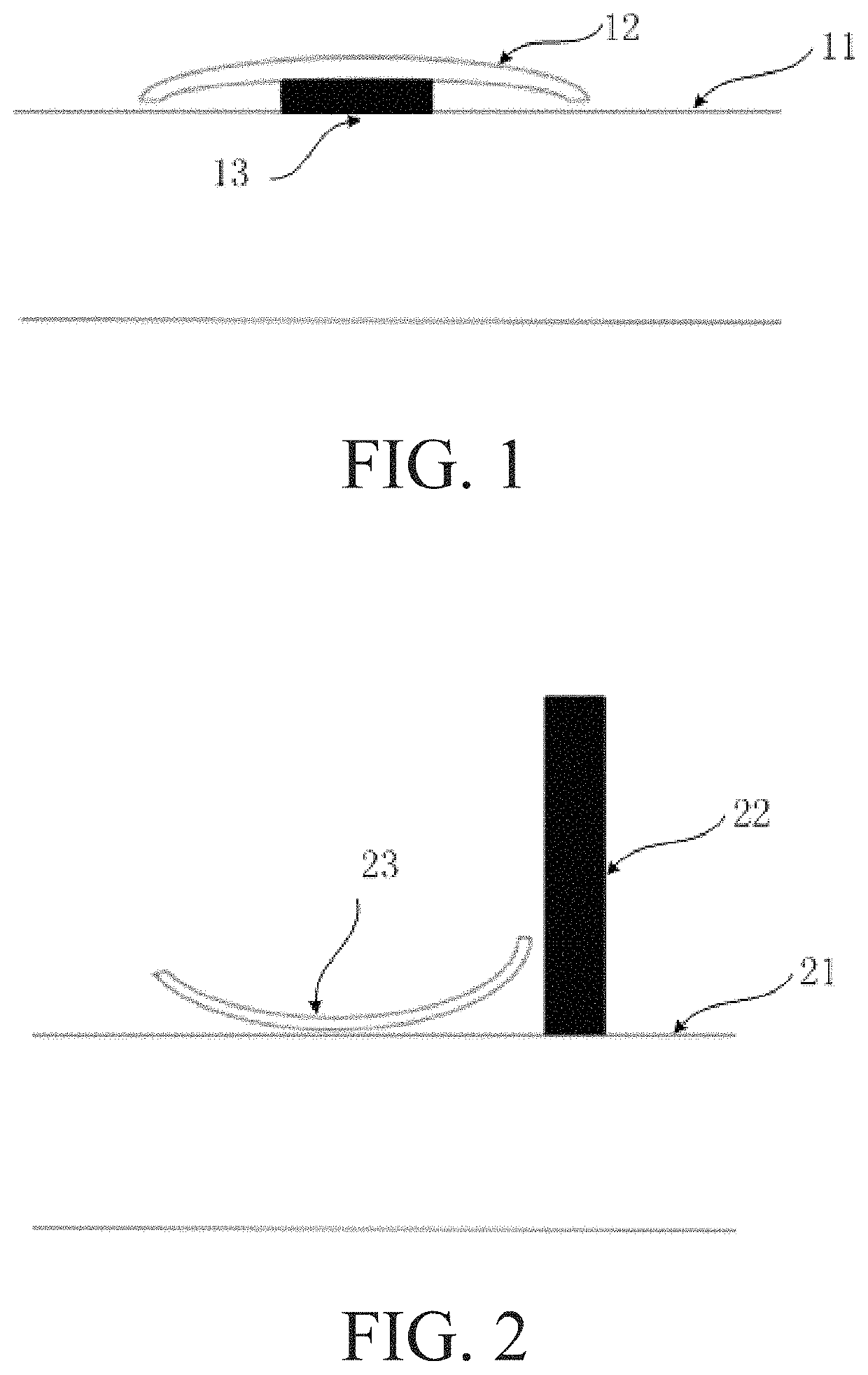
Active Publication Date: 2020-11-17
WUHAN CHINA STAR OPTOELECTRONICS TECH CO LTD
View PDF12 Cites 0 Cited by
  • Summary
  • Abstract
  • Description
  • Claims
  • Application Information

AI Technical Summary

Benefits of technology

The solution achieves measurement precision of 0.001 mm and reduces errors to within 3 um, allowing for automatic data recording and efficient measurement of large batches, addressing the limitations of manual methods.

Problems solved by technology

For liquid crystal display (LCD) panel industries, during manufacture of a polarizer and a glass substrate, because pressures on top and bottom film layers are different, the polarizer and the glass substrate are liable to be curved, which affects the final quality of products.
Such surface flatness measuring method employing the thick gauge or steel ruler has issues of lower measurement precision (about 0.1 mm), manual measurement, manual recording, great measurement error, and lack of capability of uploading measurement data.

Method used


Image

  • Surface flatness measuring device and surface flatness measuring method
  • Surface flatness measuring device and surface flatness measuring method
  • Surface flatness measuring device and surface flatness measuring method

Examples


Embodiment Construction

[0019]Embodiments of the present invention will be described in details. Examples of the embodiments are illustrated in the accompanying drawings. The same or similar reference characters refer to the same or similar elements or elements including the same or similar functions. The following embodiments described with reference to the accompanying drawings are exemplary, are only configured to construe the present invention and cannot be understood as limitations to the present invention.

[0020]In the present invention, it should be noted that unless clear rules and limitations otherwise exist, words “a first feature is “on” or “under” a second feature” can include a direct contact of the first and second features, can also include a contact of the first and second features through another feature therebetween instead of a direct contact. Furthermore, words “the first feature is “above” or “over” the second feature include that the first feature is right above or obliquely above the ...


PUM


Abstract

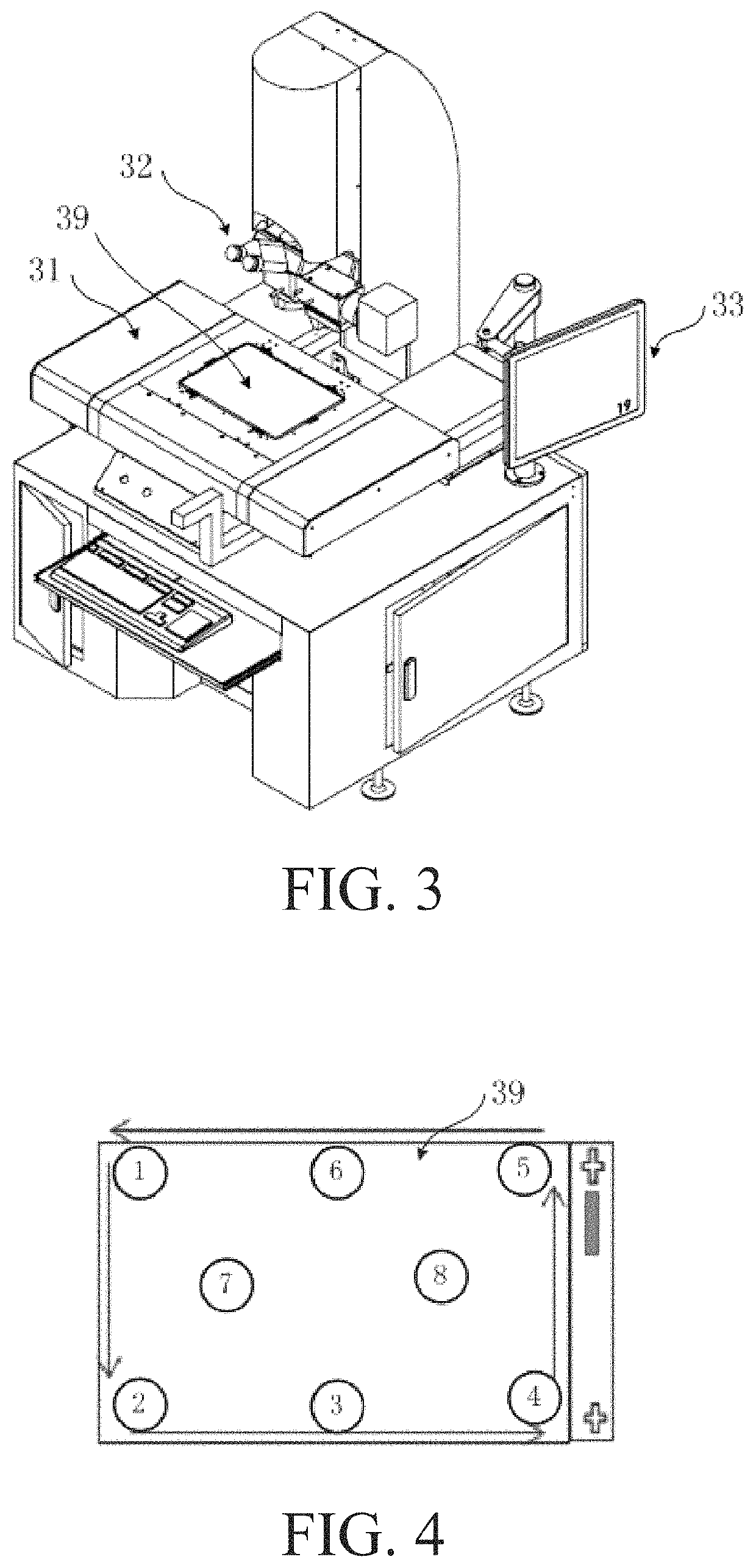
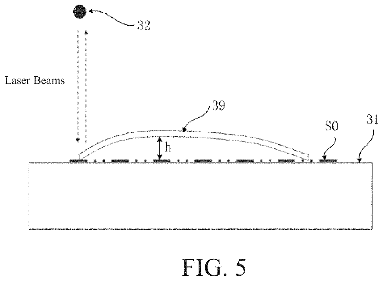
A surface flatness measuring device and a surface flatness measuring method are disclosed. By non-contacting laser measurement, measurement precision can reach 0.001 mm so the measurement precision is high. A repetitive measurement error thereof can be controlled to be within 3 um so the measurement error is tiny, which prevent issues of low measurement precision and great measurement errors due to manual measurement in prior art. At the same time, the present invention measurement data can be automatically recorded and saved, measurement for a large batch of boards under measurement can be implemented, which prevents the issues of the conventional measurement data requiring manual recording and lacking capability of uploading the measurement data.

Description

RELATED APPLICATIONS[0001]This application is a National Phase of PCT Patent Application No. PCT / CN2018 / 122620 having International filing date of Dec. 21, 2018, which claims the benefit of priority of Chinese Patent Application No. 201811395350.7 filed on Nov. 22, 2018. The contents of the above applications are all incorporated by reference as if fully set forth herein in their entirety.FIELD AND BACKGROUND OF THE INVENTION[0002]The present invention relates to fields of measurement technologies, especially to a surface flatness measuring device and a surface flatness measuring method.[0003]For liquid crystal display (LCD) panel industries, during manufacture of a polarizer and a glass substrate, because pressures on top and bottom film layers are different, the polarizer and the glass substrate are liable to be curved, which affects the final quality of products. To ensure the quality of products, it is necessary to monitor surface flatness of the polarizer and the glass substrat...

Claims


Application Information

Patent Timeline
Patent Type & Authority Patents(United States)
IPC IPC(8): G01B11/24G01B11/06
CPCG01B11/2408G01B11/0608G01B11/30G01B11/306G01B11/026G02F1/1309
Inventor ZHANG, JINPENG
Owner WUHAN CHINA STAR OPTOELECTRONICS TECH CO LTD
Learn More