Burner for a gas turbine

a gas turbine and burner technology, applied in the direction of burners, combustion processes, lighting and heating apparatus, etc., can solve the problems of less efficient atomisation than at full load operation, less efficient mixing of fuel with air, formation of carbon build-up, etc., to achieve efficient atomisation of liquid fuel and efficient mixing of fuel.

Active Publication Date: 2020-11-17
SIEMENS ENERGY GLOBAL GMBH & CO KG
View PDF8 Cites 0 Cited by
  • Summary
  • Abstract
  • Description
  • Claims
  • Application Information

AI Technical Summary

Benefits of technology

[0006]It is therefore an object of the invention to provide a burner that can be operated at a part load operation with an efficient atomisation of a liquid fuel and an efficient mixing of the fuel with air.
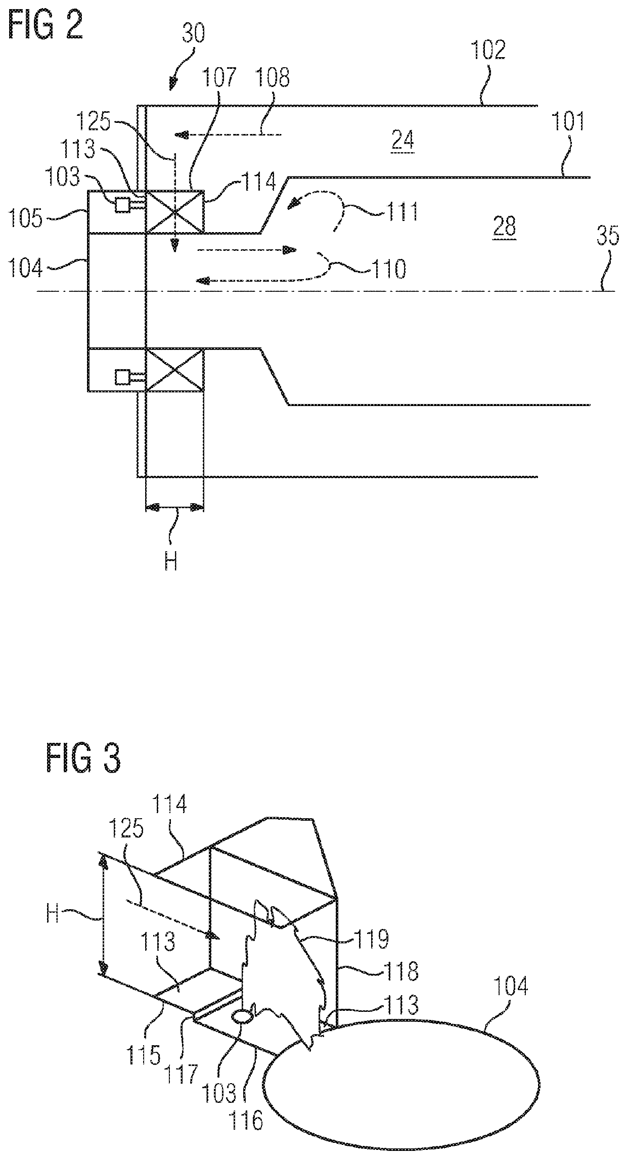
[0007]The burner according to the invention for a gas turbine engine comprises a combustion chamber and a swirler adapted to guide a swirler air flow to the combustion chamber, wherein the swirler comprises a first wall confining the swirler air flow as well as a second wall confining the swirler air flow on the same side as and downstream with respect to the swirler air flow from the first wall and being displaced with respect to the first wall in a direction away from the swirler air flow so that a step being able to cause a flow separation of the swirler air flow is formed by the first wall and the second wall, wherein the second wall has a through hole in its surface adapted to inject a liquid fuel into the swirler air flow. The flow separation caused by the step causes the formation of a multitude of vortices as part of a shear layer downstream with respect to the swirler air flow. Since the liquid fuel is injected via the through hole into the swirler air flow and not by a lance that would protrude from the second wall, the liquid fuel is directly mixed with the air when exiting the second wall and therefore interacts with the vortices. This interaction leads to an efficient atomisation of the liquid fuel and an efficient mixing with air. The atomisation and the mixing will also be efficient at a part load operation of the burner when the pressure drop of the liquid fuel over the through hole is lower than at a full load operation of the burner. Furthermore, the through holes require a smaller pressure drop than the lances. Also for this reason an efficient atomisation of the liquid fuel can take place at low part loads.
[0008]It is advantageous that the swirler comprises at least one further wall confining the swirler air flow on the same side as and downstream with respect to the swirler air flow from the second wall, wherein each of the further walls is displaced with respect to its directly adjacent and with respect to the swirler air flow upstream wall in a direction away from the swirler air flow so that a respective step being able to cause a flow separation of the swirler air flow is formed by two directly adjacent walls, wherein each further wall has a through hole in its surface adapted to inject the liquid fuel into the swirler air flow. The further walls with the further through holes increase the efficiency of the atomisation and the mixing further.
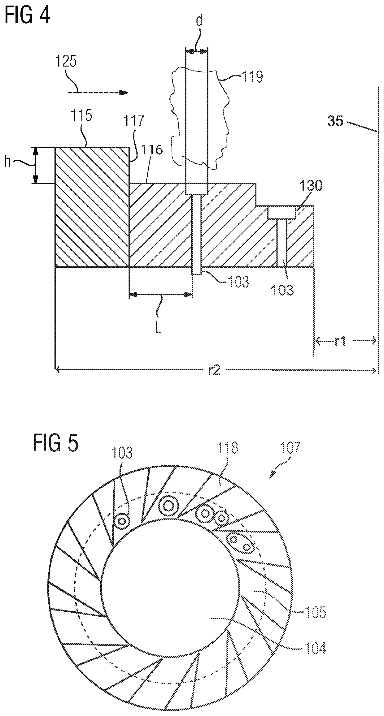
[0009]The distance between two neighboured steps is advantageously at least 2*L, wherein L is the distance from the step to its closet downstream through hole with respect to the swirler air flow downstream and closest through hole. This length ensures an efficient interaction of the liquid fuel with the vortex. It is advantageous that the swirler comprises a multitude of swirler sectors confining the swirler air flow and shaped to cause an angular momentum of the swirler air flow, wherein the swirler sectors are in contact with each of the walls. This advantageously avoids an overhanging part of the swirler sectors with the walls.
[0010]The step is advantageously located at a radial distance from the burner axis which is from r1+0.2*(r2−r1) to r1+0.8*(r2−r1), wherein r2-r1 is the distance from the radial inner end of the swirler sectors to the radial outer end of the swirler sectors. In case the combustion chamber is essentially rotationally symmetric around a burner axis, r1 and r2 can be measured from the burner axis. The lower boundary advantageously ensures an efficient interaction of the liquid fuel injected by the with respect to the swirler air flow most downstream through hole with the vortex. The upstream boundary advantageously ensures the formation of the vortex. It is advantageous that the height of each step is from 0.2*L to 0.5*L, wherein L is the distance from the step to its closest downstream through hole. This height advantageously ensures the formation of the vortex that is efficiently interacting with the liquid fuel. It is advantageous that L is from 4 mm to 20 mm, in particular from 4 mm to 8 mm. It is advantageous that the height of each step is at least 1 mm. This height advantageously ensures the formation of the shear layer. It is advantageous that the height of each step is maximum 15% of the swirler channel height, wherein the swirler channel height is the distance from the swirler air flow upstream wall forming the step to an opposite wall confining the swirler air flow and facing towards the upstream wall with respect to the swirler air flow upstream wall forming the step. This maximum height advantageously avoids a large pressure drop of the swirler air flow when passing the step. The diameter of the through hole is advantageously from 0.5 mm to 3 mm.

Problems solved by technology

However, when the burner is operated at a part load operation, the pressure drop over the lances is lower in comparison to the full load operation, which results in a less efficient atomisation than at the full load operation.
This leads to a less efficient mixing of the fuel with air and can lead to the formation of fuel ligaments that are deposited on surfaces of the burner where it leads to the formation of a carbon build-up.
When the carbon build-up is formed on the lances it can lead to an obstruction of the fuel and when this carbon build-up is formed at an igniter-port it can lead to a reduction in the efficiency of ignition.
Furthermore, the less efficient mixing of the fuel with air can lead to the formation of soot that is emitted into the atmosphere.
However, this operation is disadvantageous since it reduces the efficiency of the gas turbine and can not be performed at a part load of less than for example 40% of the full load.

Method used


Image

  • Burner for a gas turbine
  • Burner for a gas turbine
  • Burner for a gas turbine

Examples


Embodiment Construction

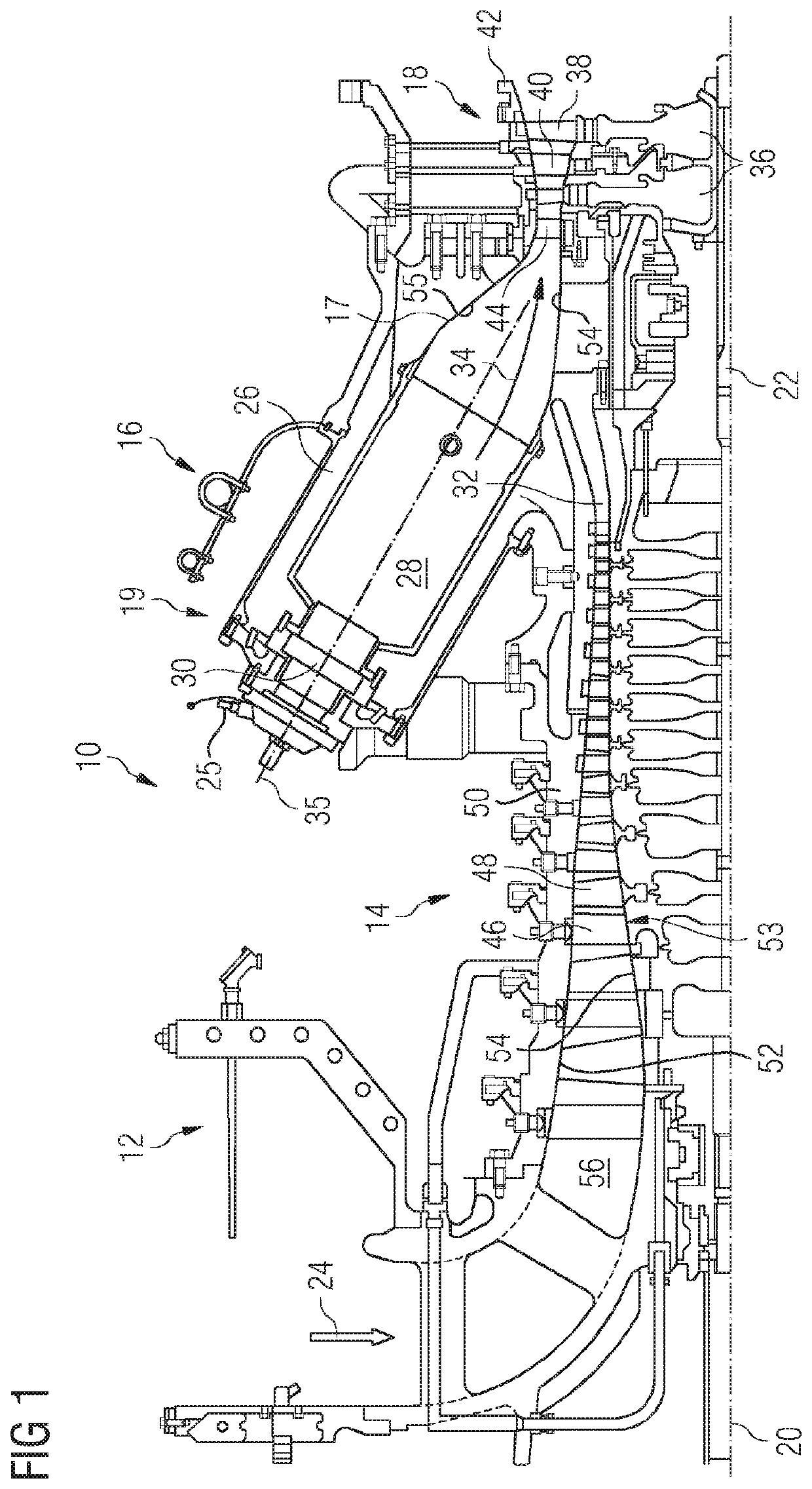
[0019]FIG. 1 shows an example of a gas turbine engine 10 in a sectional view. The gas turbine engine 10 comprises, in flow series, an inlet 12, a compressor section 14, a combustor section 16 and a turbine section 18 which are generally arranged in flow series and generally about and in the direction of a longitudinal or rotational axis 20. The gas turbine engine 10 further comprises a shaft 22 which is rotatable about the rotational axis 20 and which extends longitudinally through the gas turbine engine 10. The shaft 22 drivingly connects the turbine section 18 to the compressor section 14.

[0020]In operation of the gas turbine engine 10, air 24, which is taken in through the air inlet 12 is compressed by the compressor section 14 and delivered to the combustion section or burner section 16. The burner section 16 comprises a burner plenum 26, one or more combustion chambers 28 and at least one burner 30 fixed to each combustion chamber 28. The combustion chambers 28 and the burners ...


PUM


Abstract

A burner for a gas turbine engine has a combustion chamber and a swirler adapted to guide a swirler air flow to the combustion chamber, wherein the swirler has a first wall confining the swirler air flow as well as a second wall confining the swirler air flow on the same side as and downstream with respect to the swirler air flow from the first wall and being displaced with respect to the first wall in a direction away from the swirler air flow so that a step being able to cause a flow separation of the swirler air flow is formed by the first wall and the second wall, wherein the second wall has a through hole in its surface adapted to inject a liquid fuel into the swirler air flow.

Description

CROSS REFERENCE TO RELATED APPLICATIONS[0001]This application is the US National Stage of International Application No. PCT / EP2016 / 063286 filed Jun. 10, 2016, and claims the benefit thereof. The International Application claims the benefit of European Application No. EP15176504 filed Jul. 13, 2015. All of the applications are incorporated by reference herein in their entirety.FIELD OF INVENTION[0002]The invention relates to a burner for a gas turbine.BACKGROUND OF INVENTION[0003]A burner for a gas turbine can be operated at certain operating conditions by injecting water into the combustion chamber in order to reduce the flame temperature and therefore reducing the emission of NON. An alternative approach for reducing the emission of NOx lies in using dry low emission (DLE) burners that are operated without the injection of water and are based on premixing fuel and air prior to combustion. DLE burners emit low concentrations of NOx and produce compact flames. However, the DLE burner...

Claims


Application Information

Patent Timeline
Patent Type & Authority Patents(United States)
IPC IPC(8): F23R3/14F23R3/20F23R3/28
CPCF23R3/286F23R3/14F23R3/20F23D2900/14701
Inventor BULAT, GHENADIE
Owner SIEMENS ENERGY GLOBAL GMBH & CO KG
Why Eureka
Try Eureka