Burner for a gas turbine

a gas turbine and burner technology, applied in the direction of indirect carbon-dioxide mitigation, combustion process, lighting and heating apparatus, etc., can solve the problems of less efficient atomisation than at full load operation, less efficient mixing of fuel with air, formation of carbon build-up, etc., to achieve special efficiency of heat transfer to the liquid fuel, simple and cost-efficient technique, the effect of improving the efficiency of heat transfer

Inactive Publication Date: 2018-07-12
SIEMENS AG
View PDF0 Cites 1 Cited by
  • Summary
  • Abstract
  • Description
  • Claims
  • Application Information

AI Technical Summary

Benefits of technology

[0010]It is advantageous that the wall with the channel is formed by electronic discharge machining, selective laser sintering and/or selective laser melting. With these techniques it is advantageously possible to form channels with complex geometries with many curves. With these complex geometries it is possible to bring a long section of the channel close to the surface, hence making the heat transfer to the liquid fuel particularly efficient. The wall advantageously comprises two joint plates, wherein each plate comprises recesses that form a part of the channel. The recesses in the plates can be formed by milling that is advantageously a simple and cost-efficient technique. It is advantageous that the channel has the shape of a spiral. It is advantageous that the channel has a meandering shape. With both shapes it is possible to bring a long section of the channel close to the surface, hence making the heat transfer to the liquid fuel particularly efficient.
[0011]It is advantageous that the burner comprises a compressor for compressing the air before it enters the combustion chamber, whereby the temperature of the air raises and the compressor forms the preheating device. By preheating the air in this manner, it is advantageously achieved that the air is sufficiently hot for preheating the liquid fuel.
[0012]The burner comprises advantageously a further wall confining the swirler air flow on the same side as and upstream with respect to the swirler air flow from the wall and being displaced with respect to the wall in a direction towards the swirler air flow so that a step being able to cause a flow separation of the swirler air flow is formed by the wall and the further wall. Th...

Problems solved by technology

However, when the burner is operated at a part load operation, the pressure drop over the lances is lower in comparison to the full load operation, which results in a less efficient atomisation than at the full load operation.
This leads to a less efficient mixing of the fuel with air and can lead to the formation of fuel ligaments that are deposited on surfaces of the burner where it leads to the formation of a carbon build-up.
When the carbon build-up is formed...

Method used


Image

  • Burner for a gas turbine
  • Burner for a gas turbine
  • Burner for a gas turbine

Examples


Embodiment Construction

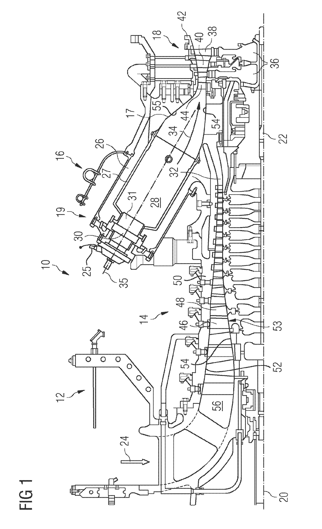
[0024]FIG. 1 shows an example of a gas turbine engine 10 in a sectional view. The gas turbine engine 10 comprises, in flow series, an inlet 12, a compressor section 14, a combustor section 16 and a turbine section 18 which are generally arranged in flow series and generally about and in the direction of a longitudinal or rotational axis 20. The gas turbine engine 10 further comprises a shaft 22 which is rotatable about the rotational axis 20 and which extends longitudinally through the gas turbine engine 10. The shaft 22 drivingly connects the turbine section 18 to the compressor section 14.

[0025]In operation of the gas turbine engine 10, air 24, which is taken in through the air inlet 12 is compressed by the compressor section 14 and delivered to the combustion section or burner section 16. As part of the compression process, the air temperature is normally raised from ambient temperature to approximately 400-400° C., along with the raise in air pressure. The burner section 16 comp...


PUM


Abstract

A burner for a gas turbine, wherein the burner has a combustion chamber, a preheating device adapted to preheat air before it enters the combustion chamber and a swirler adapted to guide a swirler air flow that has the preheated air to the combustion chamber, wherein the swirler has a base plate with a surface that confines the swirler air flow, wherein the surface has a hole adapted to inject a liquid fuel into the swirler air flow and the base plate has a channel for transporting the liquid fuel to the hole, wherein at least a part of the channel is oriented essentially parallel to the surface so that the liquid fuel streams essentially parallel to the surface and is preheated by the swirler air flow.

Description

CROSS REFERENCE TO RELATED APPLICATIONS[0001]This application is the US National Stage of International Application No. PCT / EP2016 / 066333 filed Jul. 8, 2016, and claims the benefit thereof. The International Application claims the benefit of European Application No. EP15176506 filed Jul. 13, 2015. All of the applications are incorporated by reference herein in their entirety.FIELD OF INVENTION[0002]The invention relates to a burner for a gas turbine.BACKGROUND OF INVENTION[0003]A burner for a gas turbine can be operated at certain operating conditions by injecting water into the combustion chamber in order to reduce the flame temperature and therefore reducing the emission of NOx. An alternative approach for reducing the emission of NOx lies in using dry low emission (DLE) burners that are operated without the injection of water and are based on premixing fuel and air prior to combustion. DLE burners emit low concentrations of NOx and produce compact flames. However, the DLE burners...

Claims


Application Information

Patent Timeline
IPC IPC(8): F23R3/14F23R3/28
CPCF23R3/14F23R3/286F23C7/06F23C7/004Y02E20/34
Inventor BULAT, GHENADIE
Owner SIEMENS AG
Why Eureka
Try Eureka