Method for controlling an internal combustion engine

a technology of internal combustion engine and control method, which is applied in the direction of electric control, machines/engines, mechanical apparatus, etc., can solve the problems of creating environmental disturbances, and reducing so as to reduce the environmental impact of vehicles, and reduce the operation capacity of the first gas injection system.

Active Publication Date: 2020-11-17
VOLVO LASTVAGNAR AB
View PDF20 Cites 1 Cited by
  • Summary
  • Abstract
  • Description
  • Claims
  • Application Information

AI Technical Summary

Benefits of technology

[0017]Preferably, the step of injecting the first gaseous fuel comprises injecting the first gaseous fuel into a plurality of cylinders of the cylinders. Preferably, the step of simultaneously providing the second gaseous fuel comprises simultaneously providing the second gaseous fuel for only one or two of the cylinders. Thus, in some embodiments, the method comprises providing the second gaseous fuel for only a single cylinder of the cylinders, and, in some embodiments, for only two of the cylinders. Thereby, the low load operation capacity provided by the invention will be further facilitated.
[0018]Where a first gas injection system is provided for said step of injecting the first gaseous fuel, the method preferably further comprises accumulating in a container first gaseous fuel from the first gas injection system, and supplying the second gaseous fuel for the second gaseous fuel provision at the second pressure from the container. The first gas injection system may comprise a first container, which may be a liquid natural gas (LNG) tank. Herein, the container in which first gaseous fuel may be accumulated, is also referred to as a second container. The second container, which may be part of a second gas injection system, may be a small low-pressure gas accumulator. The first gaseous fuel from the first gas injection system may be accumulated in the second container. Thereby, emissions from the first gas injection system may be reduced or avoided, thereby reducing the environmental impact of a vehicle in which the engine is operating. It should be noted that the first gas injection system may also comprise a third container in the form of a high pressure buffer tank, whereby the first gaseous fuel may be fed from the first container to the high pressure tank by means of a high pressure pump.
[0019]Thus, first gaseous fuel released from an HPGI engine or an LNG tank may be collected in the second container, where it in such embodiments in this presentation changes name to second gaseous fuel. Thereafter it may be on demand efficiently burned in the engine by switching the combustion mode in a subgroup of the cylinders from a HPGI mode to the second combustion mode.
[0020]As exemplified below, the accumulation in the second container may be provided as a result of boil-off gas received from the fuel storage tank, or upon transportation from the first gas injection system at a pressure decrease therein or during an engine stoppage. Upon such an accumulation, the gaseous fuel will be at a low pressure, and cannot be utilised as fuel in a normal HPGI combustion mode. Therefore, burning the second gaseous fuel in the second combustion mode in the second cylinder(s) will provide an effective and controllable way to utilise this fuel.
[0021]Preferably, the first gaseous fuel is injected at the first pressure into all cylinders in the first combustion mode, and subsequently a shift is made to the step of injecting the first gaseous fuel, at the first pressure, into at least the first cylinder of the cylinders, in a first combustion mode, and the step of simultaneously providing the second gaseous fuel, at the second pressure, for at least the second cylinder of the cylinders, in a second combustion mode. Such embodiments may involve on demand shifting of the combustion mode in the second subset of cylinders to a combustion process that can effectively utilise the low pressure second gaseous fuel.
[0022]Preferably, the method comprises determining a load of the engine, and performing said shift in dependence on the determined load. More specifically, the method may involve performing, in dependence on the determined load, the shifting to the step of injecting the first gaseous fuel, at the first pressure, into at least the first cylinder of the cylinders, in a first combustion mode, and the step of simultaneously providing the second gaseous fuel, at the second pressure, for at least the second cylinder of the cylinders, in a second combustion mode. In some embodiments, said shift may be performed on the condition that the load is below a load threshold value. Thereby, a condition suitable for the combustion mode shift may be identified before the shift is performed, and the shift may be avoided when power requirements of the engine provides for using all cylinders for the first combustion mode.

Problems solved by technology

Such disposal will of course create an environmental disturbance, since it involves emitting unburned hydrocarbons into the atmosphere.
In case of methane gas such emissions also cause unwanted contributions to global warming.
A problem with this solution is that a large portion, at least 30%, of the captured fuel may not be combusted in the cylinders, and therefore, the relief provided from an environmental point of view is relatively marginal.
In addition, said solution gives little possibilities for rapid control of the engine load.
Thereby, nearly all of the second fuel may be combusted.

Method used


Image

  • Method for controlling an internal combustion engine
  • Method for controlling an internal combustion engine
  • Method for controlling an internal combustion engine

Examples


Embodiment Construction

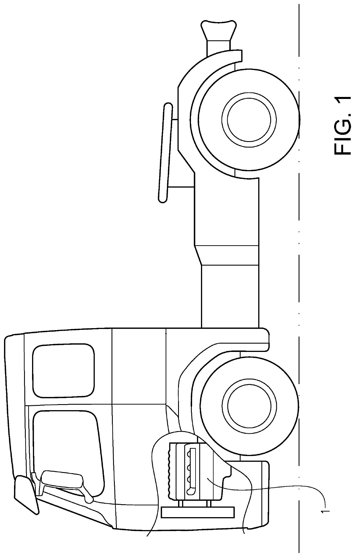
[0053]FIG. 1 shows a vehicle in the form of a truck, or a tractor for a semitrailer. It should be noted that the vehicle can be of a variety of alternative types, e.g. it may be a car, a bus, or a working machine such as a wheel loader. The vehicle comprises an engine system with a high pressure gas injection (HPG) internal combustion engine 1.

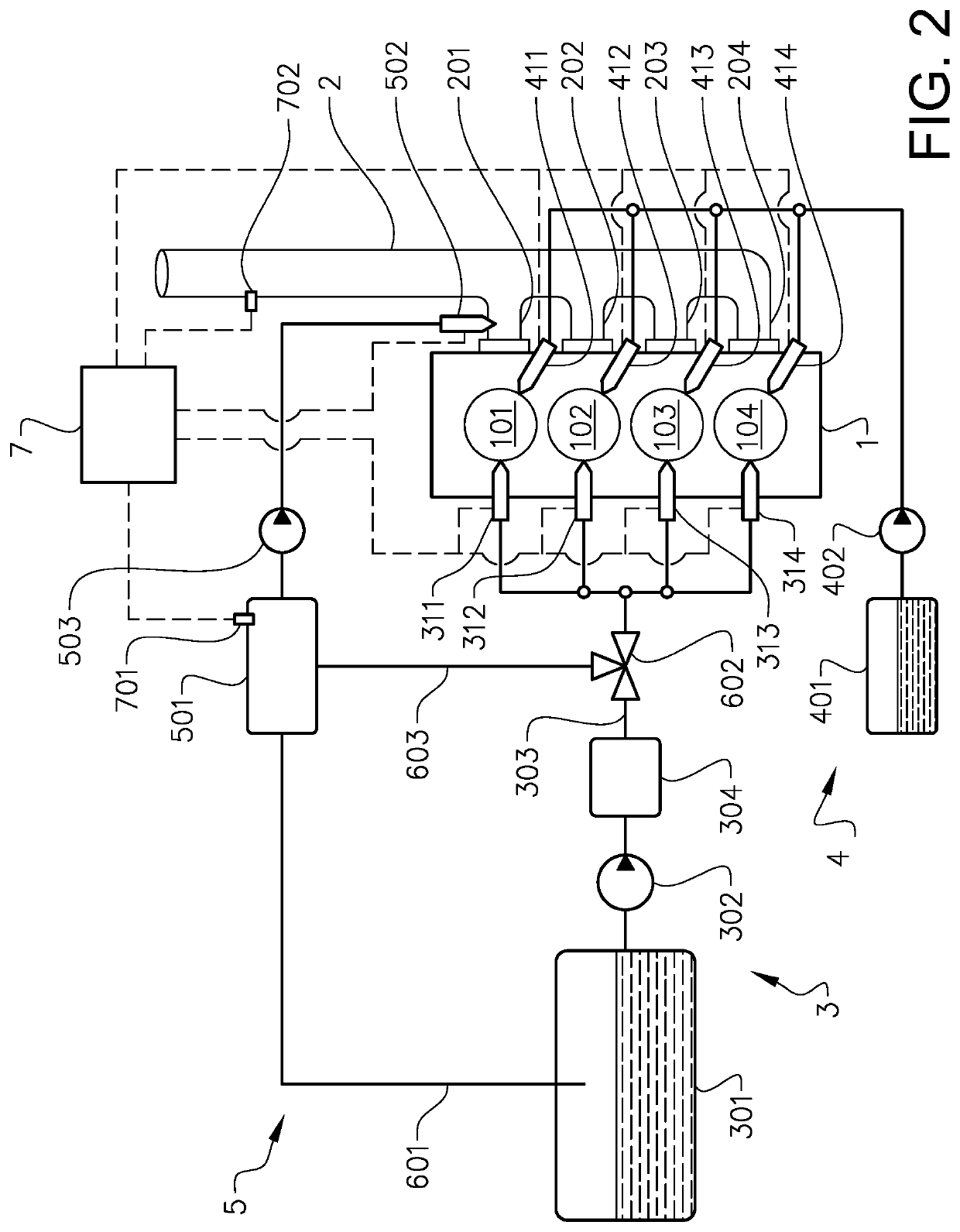
[0054]FIG. 2 depicts components of the engine system including the engine 1 which has four cylinders 101-104. The engine system comprises an air intake system 2 for the engine 1. The air intake system 2 presents for each cylinder 101-104 an air conduit 201-204 dedicated for a respective of the cylinders 101-104.

[0055]The engine system also comprises a first gas injection system 3 for injecting a first gaseous fuel into the cylinders 101-104 at a first pressure. Any suitable type of gaseous fuel may be used; in this example the first gaseous fuel is natural gas comprising methane. Other possible gases include propane and butane. The first gas i...


PUM


Abstract

A method of controlling an internal combustion engine with a plurality of cylinders includes injecting a first gaseous fuel, at a first pressure, into at least a first cylinder of the cylinders, in a first combustion mode, and simultaneously providing a second gaseous fuel, at a second pressure which is different than the first pressure, for at least a second cylinder of the cylinders, in a second combustion mode which is dissimilar to the first combustion mode, wherein the second cylinder is not the first cylinder.

Description

BACKGROUND AND SUMMARY[0001]The invention relates to a method for controlling an internal combustion engine, such as a high pressure gas injection internal combustion engine. The invention also relates to an internal combustion engine system.[0002]The invention can be applied in heavy-duty vehicles, such as trucks, buses and construction equipment, e.g. working machines. The invention can also be applied to cars. Although the invention will be described with respect to a truck, the invention is not restricted to this particular vehicle type.[0003]High Pressure Gas Injection (HPGI) internal combustion engines have been the subject of increasing interest and use for some time. The HPGI technology is also known as the High Pressure Direct Injection (HPDI) technology. It allows natural gas engines to operate at the same efficiency and power as modern heavy-duty diesel engines, but with a better fuel efficiency and reduced greenhouse gas emissions depending on the composition of the gase...

Claims


Application Information

Patent Timeline
Patent Type & Authority Patents(United States)
IPC IPC(8): F02D41/00F02D19/06F02B43/12F02M43/00F02D19/02F02B43/10F02B7/06F02M21/02F02D41/18F02D41/30F02D41/40F02M21/06F02D41/38
CPCF02D41/0025F02B43/10F02M21/0215F02D41/182F02M21/0245F02D19/024F02M21/0224F02D41/003F02D19/0692F02B43/12F02B7/06F02D41/403F02D41/401F02D41/008F02D41/0027F02M43/00F02D41/3094F02D2041/389F02D2200/10Y02T10/30F02M21/06F02B2043/103F02D19/10Y02T10/40
Inventor MAGNUSSON, INGEMARANDERSSON, ARNEANDERSSON, LENNART
Owner VOLVO LASTVAGNAR AB
Why Eureka
Try Eureka